Image forming apparatus having ink-mist blocking mechanisms

a technology of ink-mist blocking and forming apparatus, which is applied in the direction of spacing mechanisms, printing mechanisms, printing, etc., can solve the problems of contaminating the apparatus, preventing an appropriate carriage control, and the encoder sensor not being able to accurately read the linear encoder sh

Inactive Publication Date: 2011-09-22
RICOH KK
View PDF1 Cites 17 Cited by
  • Summary
  • Abstract
  • Description
  • Claims
  • Application Information

AI Technical Summary

Problems solved by technology

The ink mist may become attached to various portions of the apparatus due to the flow of air caused by the scanning movement of the carriage or by an electrostatic attractive force, thus contaminating the apparatus.
As a result, the encoder sensor may fail to read the linear encoder sheet accurately.
Such a failure to detect the carriage position affects not only the resultant image formed on the recording medium, but may also prevent an appropriate control of the carriage 1.
The failure to control the carriage 1 may result in the carriage 1, which may be moved at high speed, colliding with other components within the image forming apparatus, potentially breaking them and adversely affecting the reliability or durability of the apparatus.
Thus, the technology cannot be applied to the typical structure illustrated in FIG. 15 where the encoder sensor is installed on the carriage.
Further, the magnetic force of the magnets by which the encoder sensor and the carriage are magnetically coupled to each other may decrease over time to such an extent that the encoder sensor and the carriage cannot be accurately positioned with respect to each other.
If that happens, the carriage position cannot be accurately detected.
Thus, the problem of contamination of the linear encoder sheet is not overcome.
As a result, the linear encoder sheet may be warped or distorted, thus preventing an accurate carriage position detection.

Method used


Image

  • Image forming apparatus having ink-mist blocking mechanisms
  • Image forming apparatus having ink-mist blocking mechanisms
  • Image forming apparatus having ink-mist blocking mechanisms

Examples


Embodiment Construction

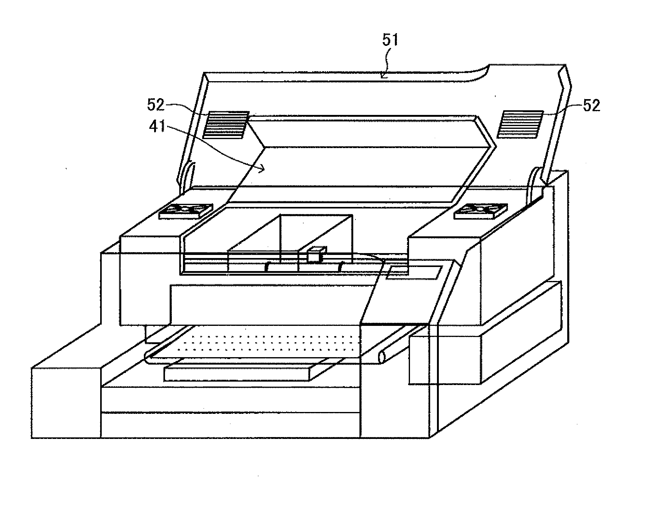
[0032]In accordance with the embodiments of the present invention, the “image forming apparatus of the fluid discharging type” refers to an apparatus that performs an image forming operation by discharging a recording fluid onto a recording medium, such as an inkjet recording apparatus. The “recording medium” may include a sheet of various material, such as paper, thread, fiber, cloth, leather, metal, plastic, glass, wood, and ceramics. “Image formation (or recording)” may refer to the process of forming (or recording) not just an image with some apparent meaning, such as characters and figures, but also an image with apparently no meaning, such as a random pattern, on the recording medium. The “recording fluid” is not limited to ink but may include a DNA sample, a resist, and a patterning material. The “image” is not limited to two-dimensional images but may refer to an image formed on a three-dimensional object, or even a three-dimensional image.

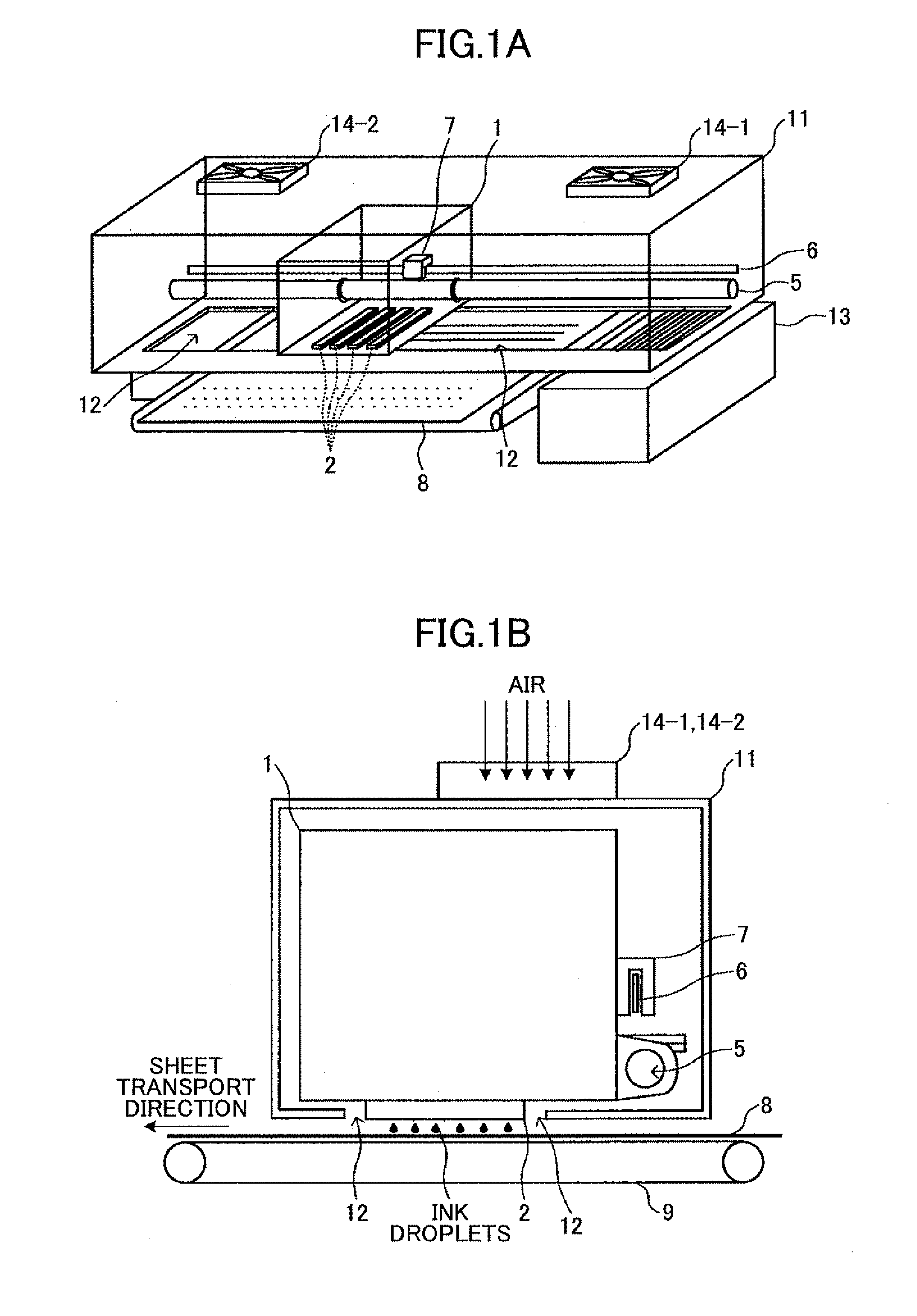
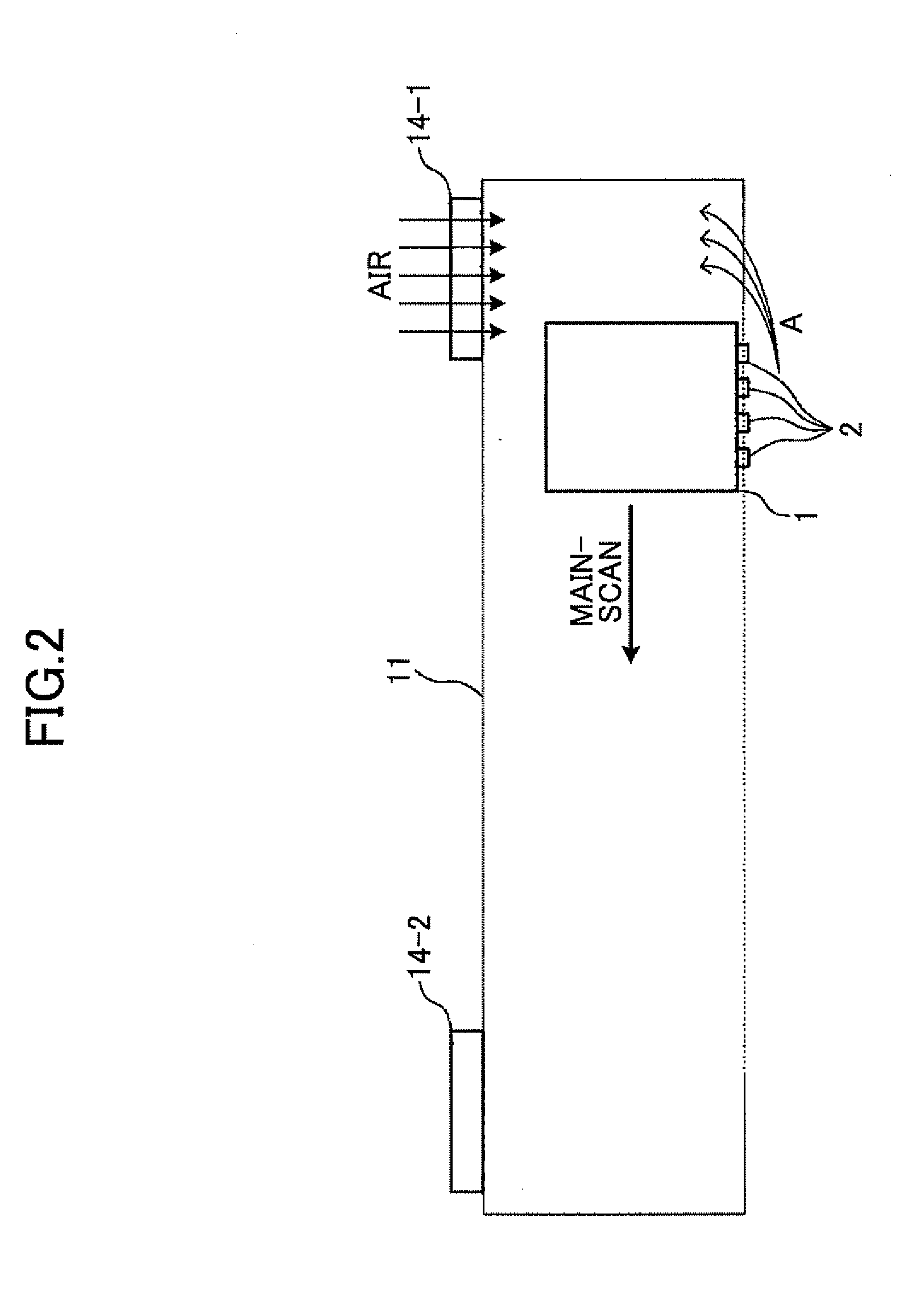
[0033]Referring now to the drawings...


PUM


Abstract

An image forming apparatus includes a printing head having an ink nozzle configured to discharge ink droplets onto a recording medium in order to form an image on the recording medium in a recording operation; a carriage on which the printing head is mounted and being moved in a main-scan direction during the recording operation; a linear encoder sheet having a counter for detecting a position of the carriage; an encoder sensor mounted on the carriage and detecting the position of the carriage by optically reading the counter of the linear encoder sheet; an carriage unit enclosure in which at least the carriage, the linear encoder sheet, and the encoder sensor are disposed; and an internal pressure adjusting unit adjusting an internal pressure of the carriage unit enclosure to be other than a negative pressure.

Description

BACKGROUND OF THE INVENTION[0001]1. Field of the Invention[0002]The present invention relates to image forming apparatuses having ink-mist blocking mechanisms.[0003]2. Description of the Related Art[0004]Image forming apparatuses include printers, facsimile machines, copy apparatuses, plotters, and multifunction peripherals, an inkjet recording apparatus is known. An inkjet apparatus is an image forming apparatus of a fluid-discharging type, which discharges ink droplets onto a sheet of recording material (“recording medium”) from a recording head in a printing operation. In a serial type of an inkjet recording apparatus, the printing operation is performed while the printing head is moved in a direction (“main-scan direction”) perpendicular to the direction of transport of the sheet (“sub-scan direction”).[0005]In the serial type of an inkjet recording apparatus, a mechanism for detecting the position of a carriage carrying the printing head and the amount of its movement is requir...

Claims


Application Information

Patent Timeline
Patent Type & Authority Applications(United States)
IPC IPC(8): B41J2/11
CPCB41J2/1714B41J29/13B41J19/202B41J2/17556
Inventor TACHIBANA, EIJI
Owner RICOH KK
Why Eureka
Try Eureka