Ventilation device

a technology of ventilation device and non-return flap, which is applied in vehicle heating/cooling devices, vehicle components, transportation and packaging, etc., can solve the problem of no longer ensuring the proper functioning of the device, and achieve the effect of improving the sealing of the non-return flap

Active Publication Date: 2011-09-22
ILLINOIS TOOL WORKS INC
View PDF12 Cites 9 Cited by
  • Summary
  • Abstract
  • Description
  • Claims
  • Application Information

AI Technical Summary

Benefits of technology

[0004]It is an object of the invention to provide a ventilation device in which the non-return flap can be mounted in a simple manner and is especially safely fastened.
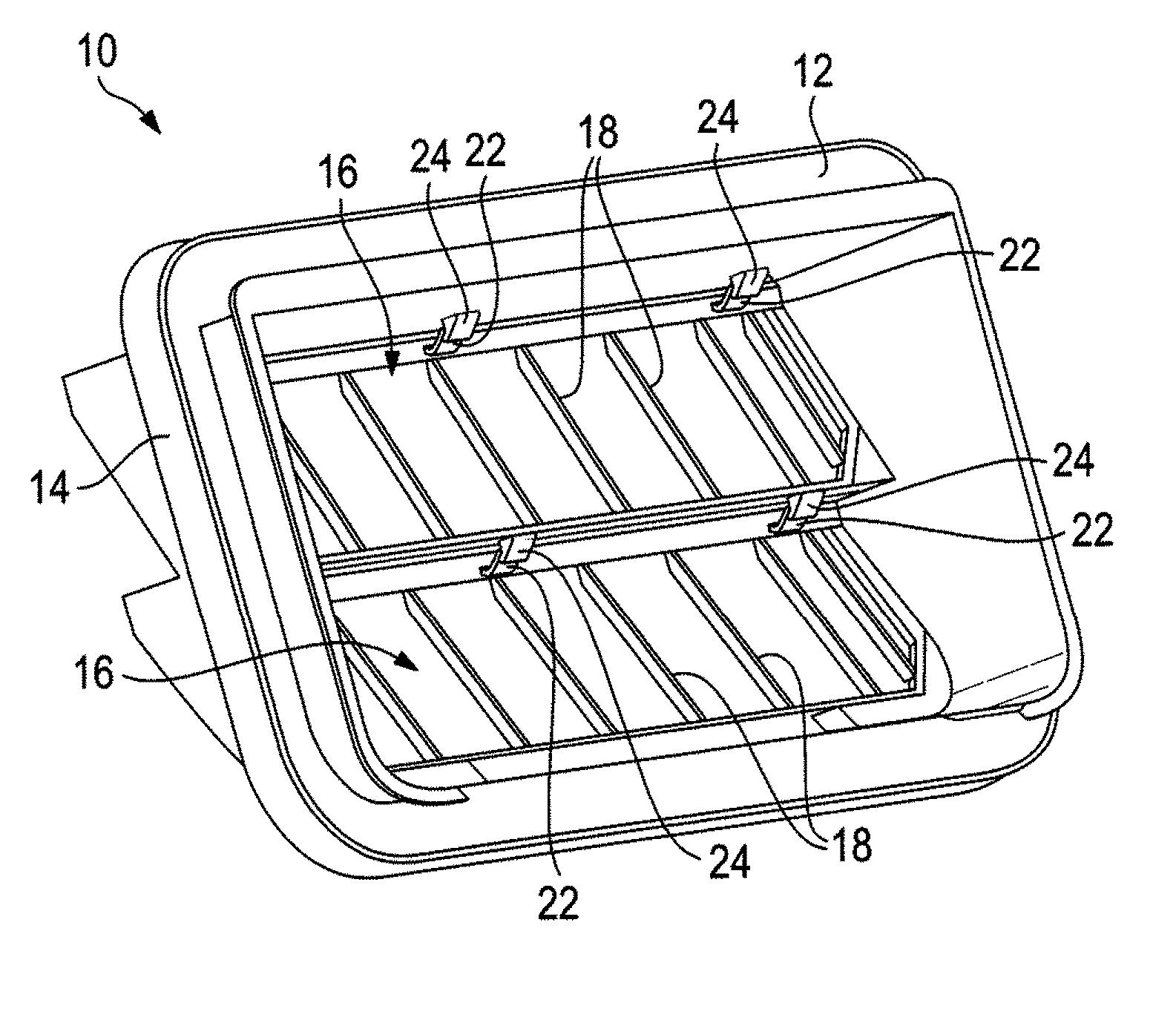
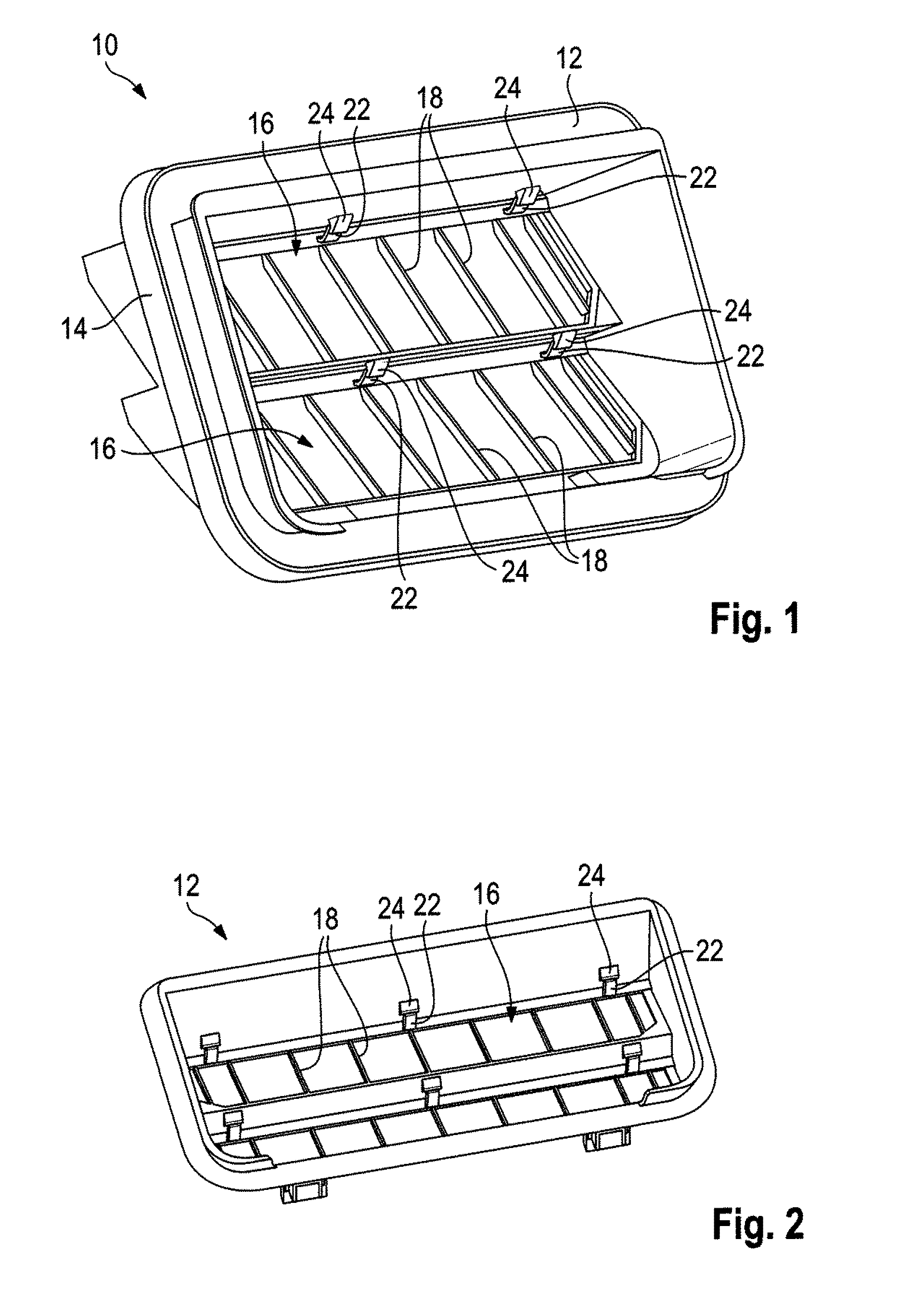
[0008]According to a preferred embodiment, provision is made that the free end of the holding member in the locked position is hooked behind a latching projection on the frame. In this way, the free end of the holding member can be locked in place particularly reliably.
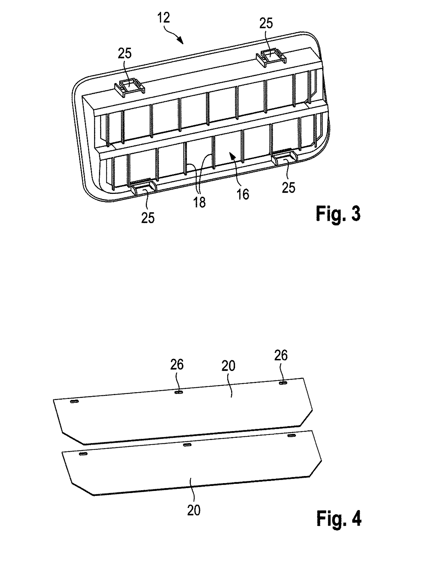
[0010]To ensure a simple shifting along the holding member, the recess of the non-return flap is preferably larger than the cross-section of the holding member, so that the non-return flap can not get jammed or stuck on the holding member.
[0012]The non-return flap may have an intermediate position, in which the flap is swiveled against the holding member, i.e. in this position the non-return flap is only swiveled and not deformed. The resistance of the non-return flap during shifting or swiveling along the holding member is lower than the force that is required to bend or deform the non-return flap. In addition, the resistance to opening of the non-return flap during swiveling is constant. Swiveling the non-return flap or shifting the non-return flap on the holding member causes the resistance put up by the non-return flap during opening of the ventilation device to be reduced, so that an exchange of air or a pressure equalization is possible already with smaller pressure differences. To move the non-return flap from the intermediate position to the fully opened position, the non-return flap can be elastically deformed, in addition to the swiveling movement.
[0013]Preferably, the holding member protrudes from the frame in the direction of flow through the ventilation device. The joint that is formed by the holding member thus protrudes in the direction of the swiveling movement of the non-return flap, so that a simple shifting of the non-return flap on the holding member is possible.
[0016]The non-return flap is preferably made from a flexible material, so that, in addition to being swiveled, it can be deformed. This improves the sealing of the non-return flap on the frame of the ventilation device.

Problems solved by technology

It has turned out, however, that in operation, the non-return flap can become detached from the holding members, so that a proper functioning is no longer ensured.

Method used


Image

  • Ventilation device
  • Ventilation device
  • Ventilation device

Examples


second embodiment

[0034]the ventilation device 10 as illustrated in FIG. 7 substantially corresponds to the embodiment illustrated in FIGS. 1 to 6. Provision is made here merely additionally for an acoustic hood 30 on the rear side of the frame 12, the acoustic hood providing for an improved sound absorption of the ventilation device 10. The acoustic hood 30 is in the form of an extension of the frame 12 here, which may be lined with foam elements, for example (not shown here), for better noise absorption.

third embodiment

[0035]The third embodiment, illustrated in FIG. 8, additionally has a further frame member 32, a so-called flutter curve, on the front face of the frame 12. In the open position of the non-return flap 20, the latter rests against the frame member 32 to prevent the non-return flap 20 from vibrating in the air flow, as a result of which noises caused by the air flowing through are reduced.


PUM


Abstract

A ventilation device (10), in particular for a vehicle interior, has a frame (12) which includes at least one opening (16), and at least one non-return flap (20), the non-return flap (20) having at least one recess (26) provided thereon through which a holding member (22) provided on the frame (12) extends, and the non-return flap (20), depending on the active pressure differential, being movably adjustable on the holding member (22) between a closed position, in which the non-return flap (20) rests against the frame (12) and closes the at least one opening (16) of the frame (12), and an open position. The holding member (22) is deformable between a mounting position, in which the non-return flap (20) can be mounted to the holding member (22), and a locked position, in which the non-return flap (20) can not be dismounted.

Description

FIELD OF THE INVENTION[0001]The present invention relates to a ventilation device, in particular for a vehicle interior.BACKGROUND OF THE INVENTION[0002]Ventilation devices serve to carry off the air supplied to the vehicle interior via a ventilation system. The ventilation device includes a frame having a non-return flap mounted therein which can open in case of an overpressure in the vehicle interior, so that air can escape from the vehicle interior. When no air flows out of the vehicle interior, the non-return flap rests against the frame, as a result of which the frame is sealed and an ingress of moisture, dirt or exhaust gases into the vehicle interior is prevented.[0003]A ventilation device of the type initially mentioned is disclosed in DE 20 2006 020 365. Pins which each have a head are used as holding members. The non-return flap is mounted on the holding members by pressing the head of the respective holding member through the recess (“buttonhole”) of the non-return flap i...

Claims


Application Information

Patent Timeline
Patent Type & Authority Applications(United States)
IPC IPC(8): B60H1/26
CPCB60H1/249B60H1/0065B60H1/00664B60H1/00835B60H1/3414
Inventor WEBER, ANDREAS
Owner ILLINOIS TOOL WORKS INC
Why Eureka
Try Eureka