Self-centering, torque-sensing joint assembly for a pallet truck power steering system

a pallet truck and torque sensor technology, applied in the direction of mechanical control devices, process and machine control, underwater equipment, etc., can solve the problems of less sensitive and accurate torque sensors, varied and inconsistent steering assistance,

Active Publication Date: 2011-09-22
RAYMOND LTD
View PDF22 Cites 23 Cited by
  • Summary
  • Abstract
  • Description
  • Claims
  • Application Information

AI Technical Summary

Problems solved by technology

Conventional steering assist systems do not account for changes in measured torque value due to tiller arm angle and thus, deliver varied and inconsistent steering assist.
For example, when a pallet truck with a conventional steering assist system is operating in very close quarters, i.e., with the steering mechanism in a near-vertical orientation, the torque sensor is least sensitive and accurate.
Another challenge for conventional power assist systems is that the motion required to steer a pallet truck changes from a lateral force applied to the handle to a twisting force on the tiller arm as the steering mechanism changes from a horizontal position to a vertical one.
This change in motion and steering force results in an inconsistent operation, level of steering assist, and ‘feel’ to the operator depending on the relative angle and position of the tiller arm and steering handle.

Method used


Image

  • Self-centering, torque-sensing joint assembly for a pallet truck power steering system
  • Self-centering, torque-sensing joint assembly for a pallet truck power steering system
  • Self-centering, torque-sensing joint assembly for a pallet truck power steering system

Examples


Embodiment Construction

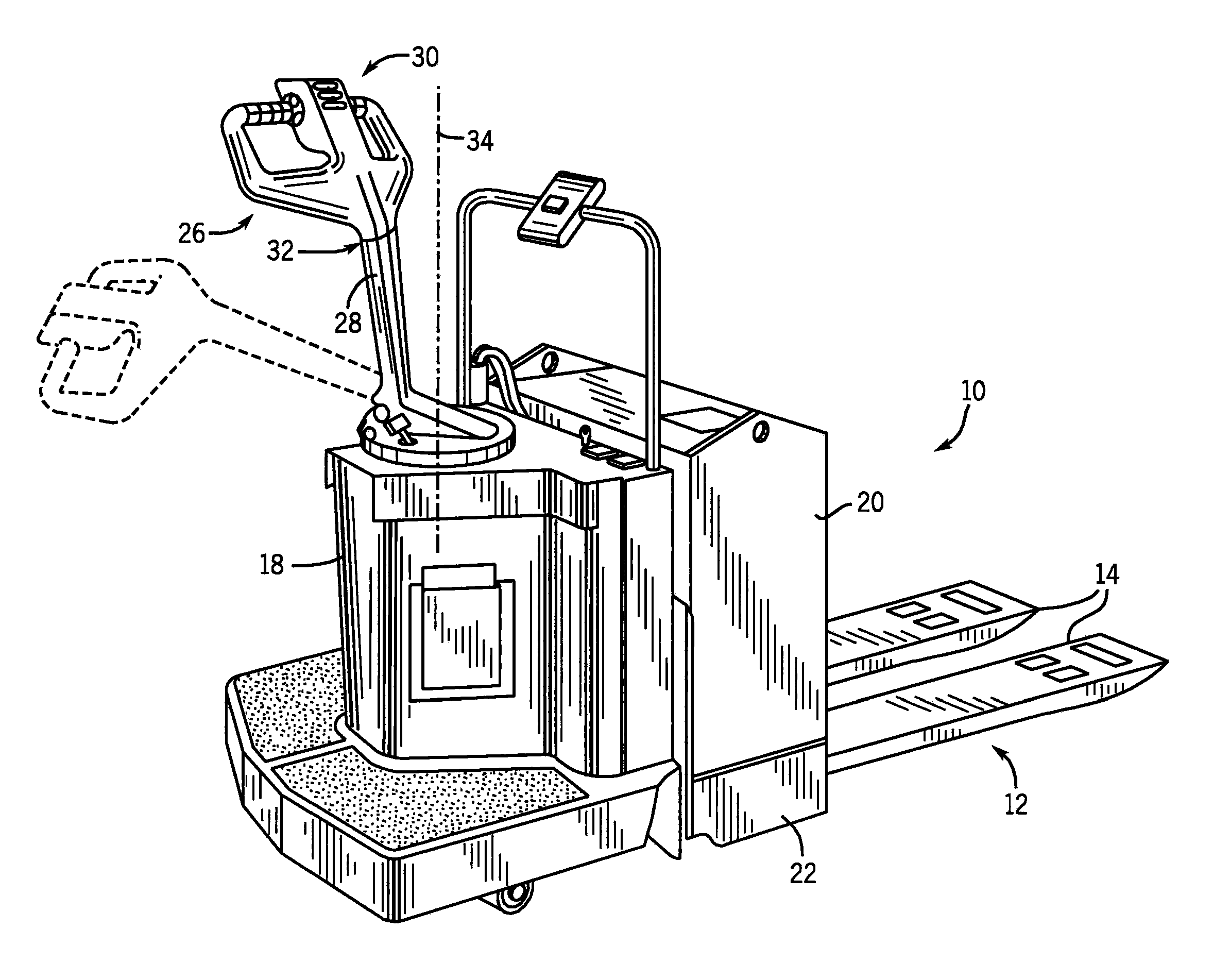
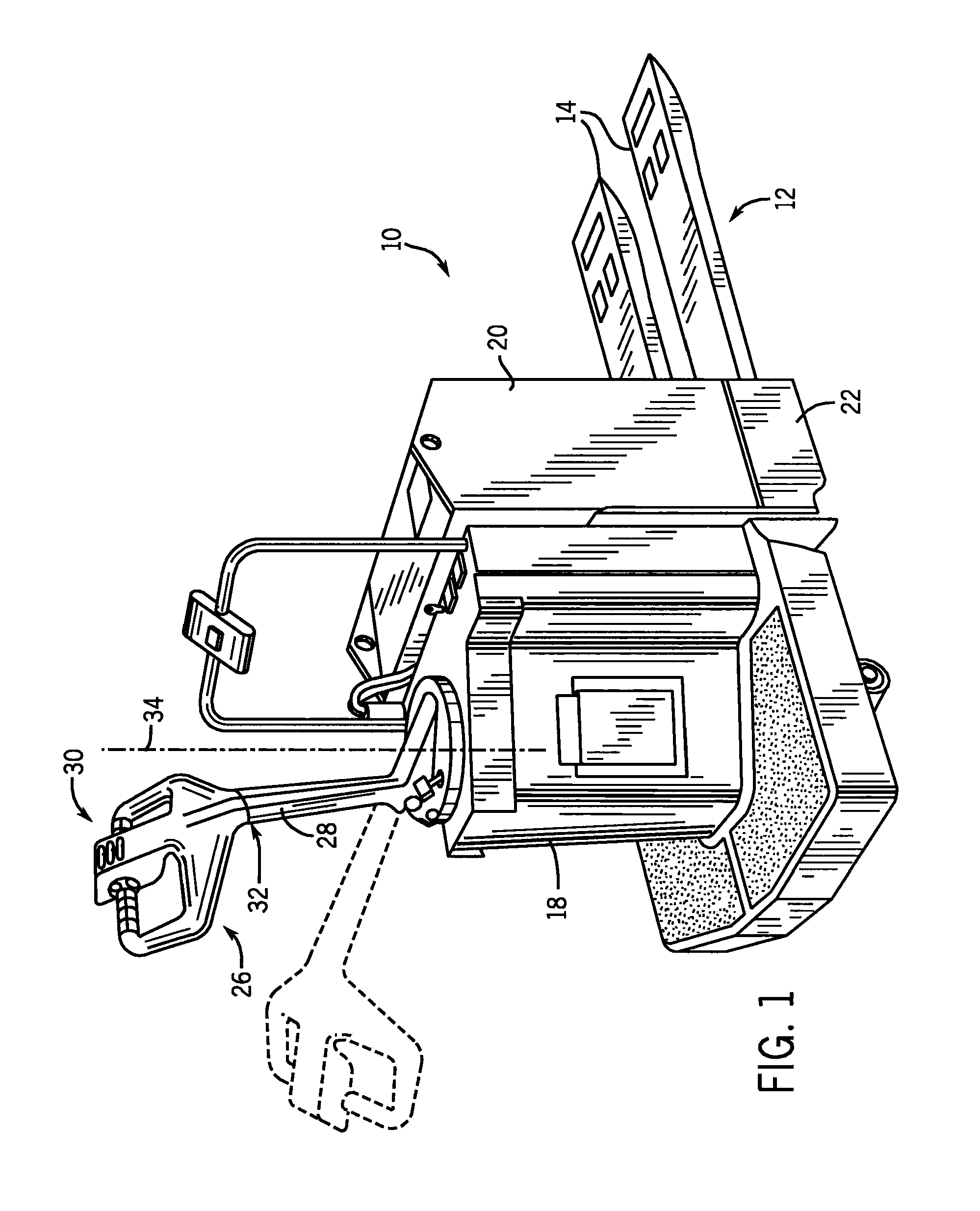
[0024]Referring now to the figures and more particularly to FIGS. 1, 8, and 9, which show a motorized hand / rider low-lift pallet truck 10 incorporating the present invention. Directional terms such as “front,”“rear,”“top,”“bottom,” and the like are used with reference to the component orientations depicted in the drawing figures. These terms are used for illustrative purposes only and, unless otherwise noted, are not intended to limit the scope of the claims.

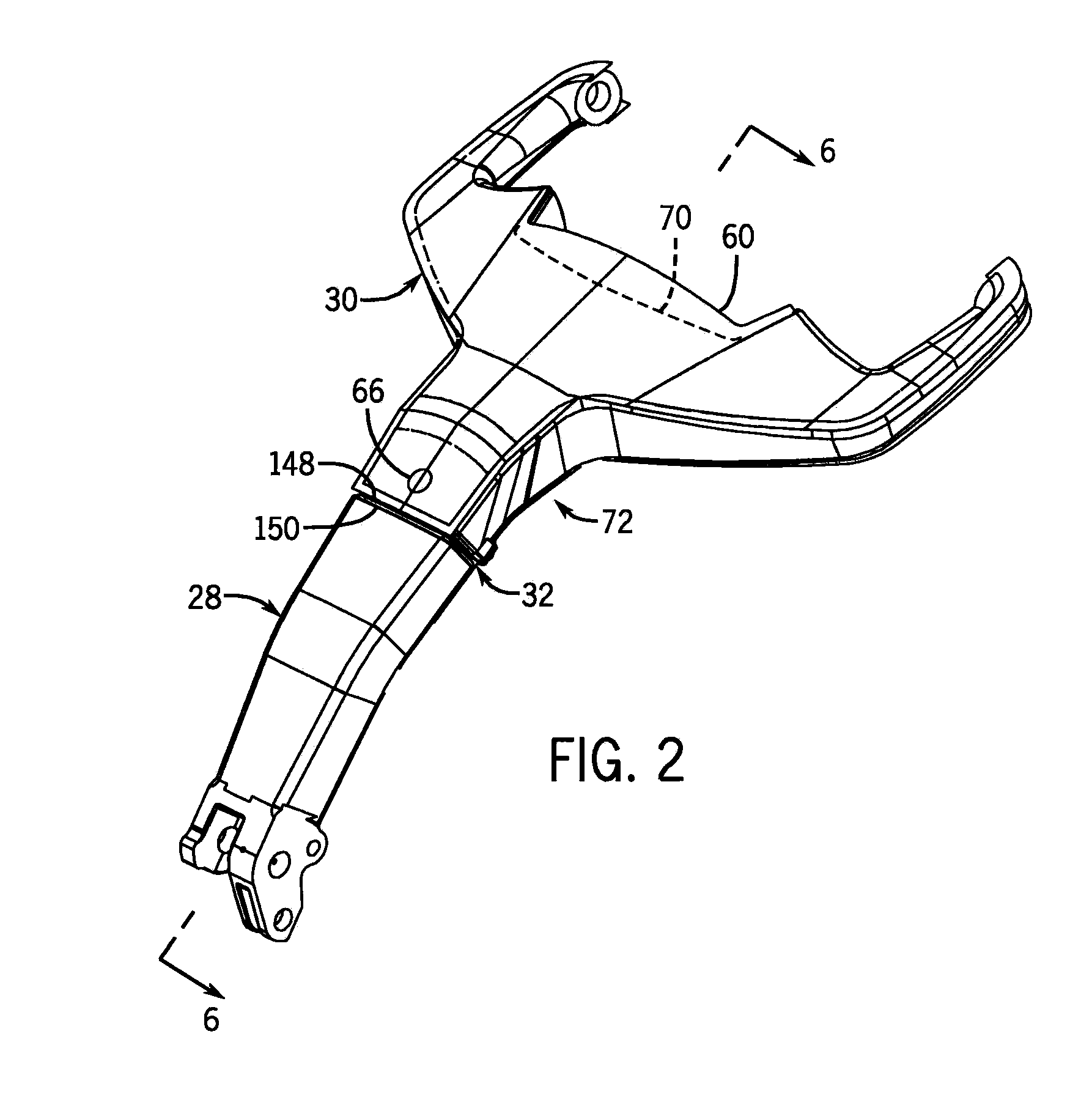
[0025]The pallet truck 10 includes a fork carriage 12 with a pair of load bearing forks 14, a traction motor 16 mounted in a motor compartment 18, a battery 20 secured in a battery compartment 22, and a steerable drive wheel 24. The drive wheel 24 is coupled to a steering mechanism 26 which includes a tiller arm 28 and a handle 30. The tiller arm 28 and handle 30 are mechanically connected via a flexible knuckle joint 32. The steering mechanism 26 is rotatable to the right and left about a steer axis 34 to steer the pallet truck...


PUM


Abstract

A steering mechanism includes a handle with a tiller arm coupled to the handle via a flexible joint allowing relative movement of the handle about the tiller arm. A handle centering mechanism forming part of the steering mechanism includes a first end fixedly secured to the handle and a second end extending into a channel of the tiller arm. The second end compresses bumpers disposed on opposing sides of the second end. The bumpers urge the handle toward a neutral position wherein when a force is applied to move the handle away from a home position relative to the tiller arm, one of the compressed bumpers of the pair of compressed bumpers is further compressed. When the force is removed, the handle is returned to the home position by action of the pair of compressed bumpers. Preferably, the steering mechanism includes a torque sensing arrangement having a sensor and a magnet. The sensor produces a signal based on movement of the handle relative to the tiller arm by sensing changes in the magnet field of the magnet proportional to the torque exerted on the handle regardless of the angle of the tiller arm.

Description

CROSS-REFERENCE TO RELATED APPLICATIONS[0001]This application is a continuation-in-part application claiming priority to U.S. patent application Ser. No. 12 / 728,521 filed on Mar. 22, 2010, and which is fully incorporated herein by reference.STATEMENT CONCERNING FEDERALLY SPONSORED RESEARCH OR DEVELOPMENT[0002]Not applicable.BACKGROUND[0003]This invention relates to power steering systems for material handling vehicles, and more particularly, to a self-centering, torque-sensing joint assembly disposed in a steering mechanism that detects operator steering intent for an electrically driven, hand-steered pallet truck regardless of angle of the steering mechanism.[0004]Industrial material handling vehicles such as electric hand-steered pallet trucks are commonly found in warehouses, factories, shipping yards, and, generally, wherever pallets, large packages, or loads of goods are required to be transported from place to place. Pallet trucks typically include load bearing forks for lifti...

Claims


Application Information

Patent Timeline
Patent Type & Authority Applications(United States)
IPC IPC(8): G06F19/00B62D1/20
CPCB62D1/14B62D5/0418B62D6/10Y10T74/20B66F9/07568Y02T10/7258B66F9/065Y02T10/72
Inventor HANNA, TIMOTHY T.DAY, RICHARD M.MCDONOUGH, JAMES M.COPPOLA, JEFFREY A.
Owner RAYMOND LTD
Why Eureka
Try Eureka