
Pressurized and heated testing chamber

a technology which is applied in the field of pressurized and heated testing chambers, can solve the problems of reducing the flow introduction rate, affecting the effect of the stimulation operation, so as to achieve the effect of quick and convenient subjecting

Active Publication Date: 2011-09-29
SAUDI ARABIAN OIL CO
View PDF20 Cites 41 Cited by
  • Summary
  • Abstract
  • Description
  • Claims
  • Application Information

AI Technical Summary

Benefits of technology

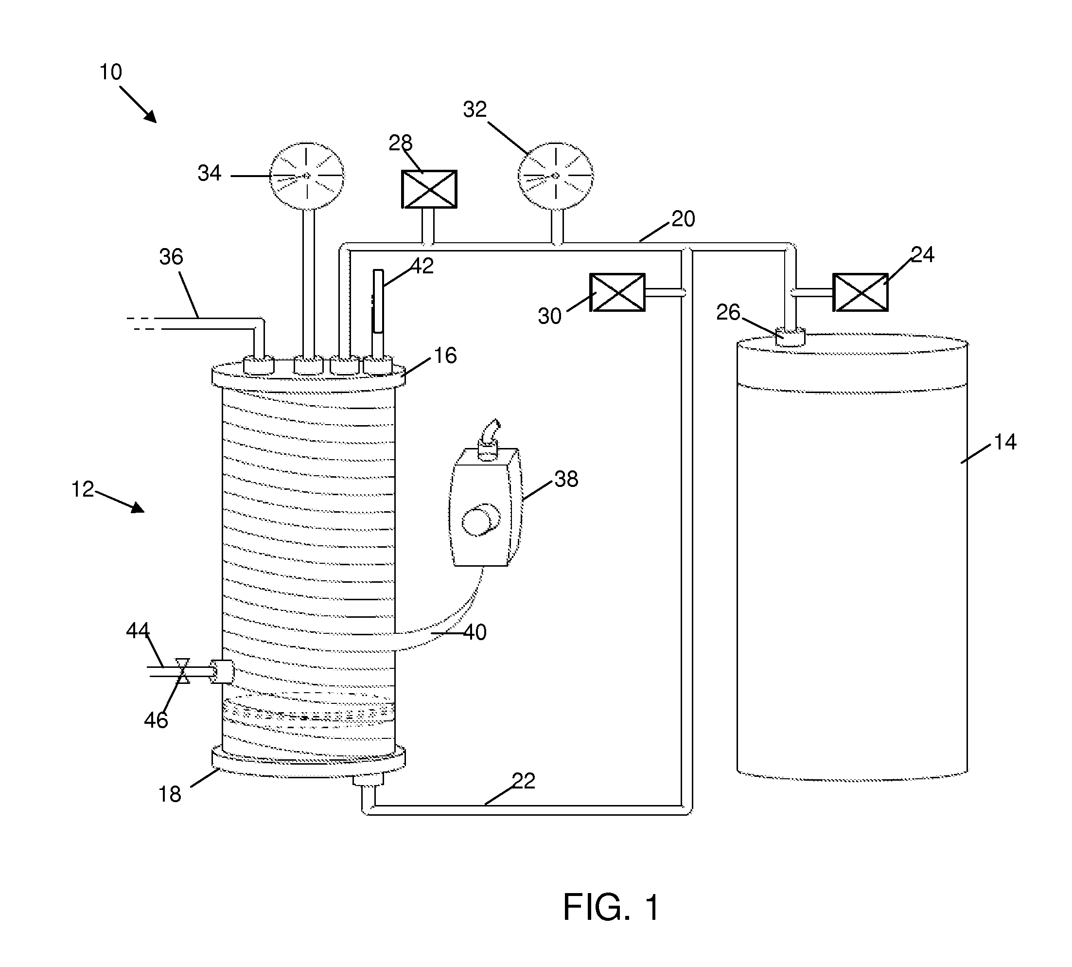
[0020]The relatively small sample chamber includes a piston closely fit within the chamber that is driven by a pressure source, such as compressed nitrogen gas from a portable nitrogen cylinder. Pressure, e.g., up to about 2000 psi, is applied via the piston to simulate conditions to which the sample chemicals would be exposed in the subterranean reservoir during the fracturing process. One or more suitable pressure gauges are connected to the sample chamber and pressure lines connecting the chamber and the pressure source. The piston is also used for clearing the sample from the chamber, to assist in cleaning the chamber, and / or to purge the chamber of air to avoid contamination.
[0023]In addition, the apparatus can be utilized in a laboratory, for instance, to conduct solubility test, gelling tests, corrosion tests, gas sampling, or compression of fluids. With the inclusion of the pressurization of the apparatus and the controlled heating capability, the sample can quickly and conveniently be subjected temperature and pressure conditions that simulate the conditions in the reservoir.

Problems solved by technology

However, if viscous gelling occurs prematurely, e.g., in the tanks and / or flowlines or otherwise before the fluid is pumped in the well, the fluid introduction rates decrease and excess pressures are encountered.
Many stimulation operations are not ideal due to various problems, including limitations associated with mixing of the stimulation fluid and incompatible chemical mixtures.
In the event that the frac chemicals are not performing properly, premature termination of the fracturing operation is required to prevent conditions dangerous to the personnel and equipment failures such as rupturing of the wellbore casing and other components in hydraulic communication with the fluid source.
A premature termination incurs substantial costs and lost time.
For instance, the frac tank itself may be contaminated, causing undesirable side reactions of the frac fluid.
In other undesirable situations, the frac fluid composition and / or mixture is not what was originally intended, e.g., due to human error in the field.
In actual frac operations at a well site, major equipment and associated potential problems are usually considered, including standby pump trucks and standby blenders.
However, quality control programs are desirable because unexpected problems can arise, which are generally much less obvious, and, while they may not terminate the treatment, these problems can ultimately compromise the efficacy of the fracturing operation.
While vendors of frac fluids and their various additives have a working knowledge of most chemical interactions, additive incompatibility nonetheless remains a problem in the industry.
For instance, one or more additives may be incompatible with the fracturing fluid, the energizing component, and / or the breaking agents under the prevailing well conditions, i.e., the high temperatures and pressures under which well stimulation occurs.
While many quality assurance and quality control programs rely on various forms and checklists which document the equipment, inventory and instrumentation available on location and after the treatment, materials used and personnel performance, the industry lacks reliable apparatus and a comprehensive protocol to accommodate the requisite testing that is required and which is preferably performed at the drilling site shortly before the frac operation is scheduled to begin.
For instance, while the aqueous fracturing fluid tested in the laboratory can be supplied directly from the vendor, fracturing fluid use in the field has been sitting in a frac tank and can become contaminated.
Historically, there is been hesitation to conduct actual on-site testing of the frac fluids due to inadequate time and resources to conduct comprehensive tests for each operation.
However, these tests may not always accurately approximate the chemical interactions between the various constituents of the frac fluid under the pressure and temperature conditions to which they will be exposed downhole.
The lack of actual on-site testing of the frac fluids can result in significant problems in the event that there is a defect in the frac fluid, e.g., contamination of the frac tank, or the frac fluid composition and / or mixture is not what was originally intended, e.g., due to human error in the field.
However, these assemblies do not solve the problems related to a lack of actual on-site testing of the frac fluids.

Method used


Image

  • Pressurized and heated testing chamber
  • Pressurized and heated testing chamber
  • Pressurized and heated testing chamber

Examples


Embodiment Construction

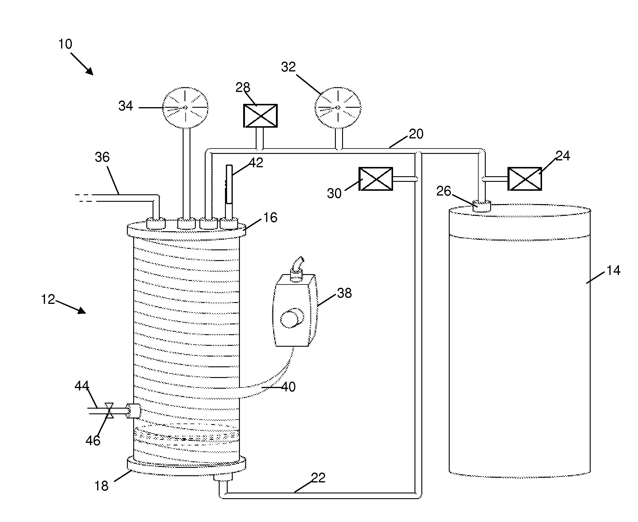
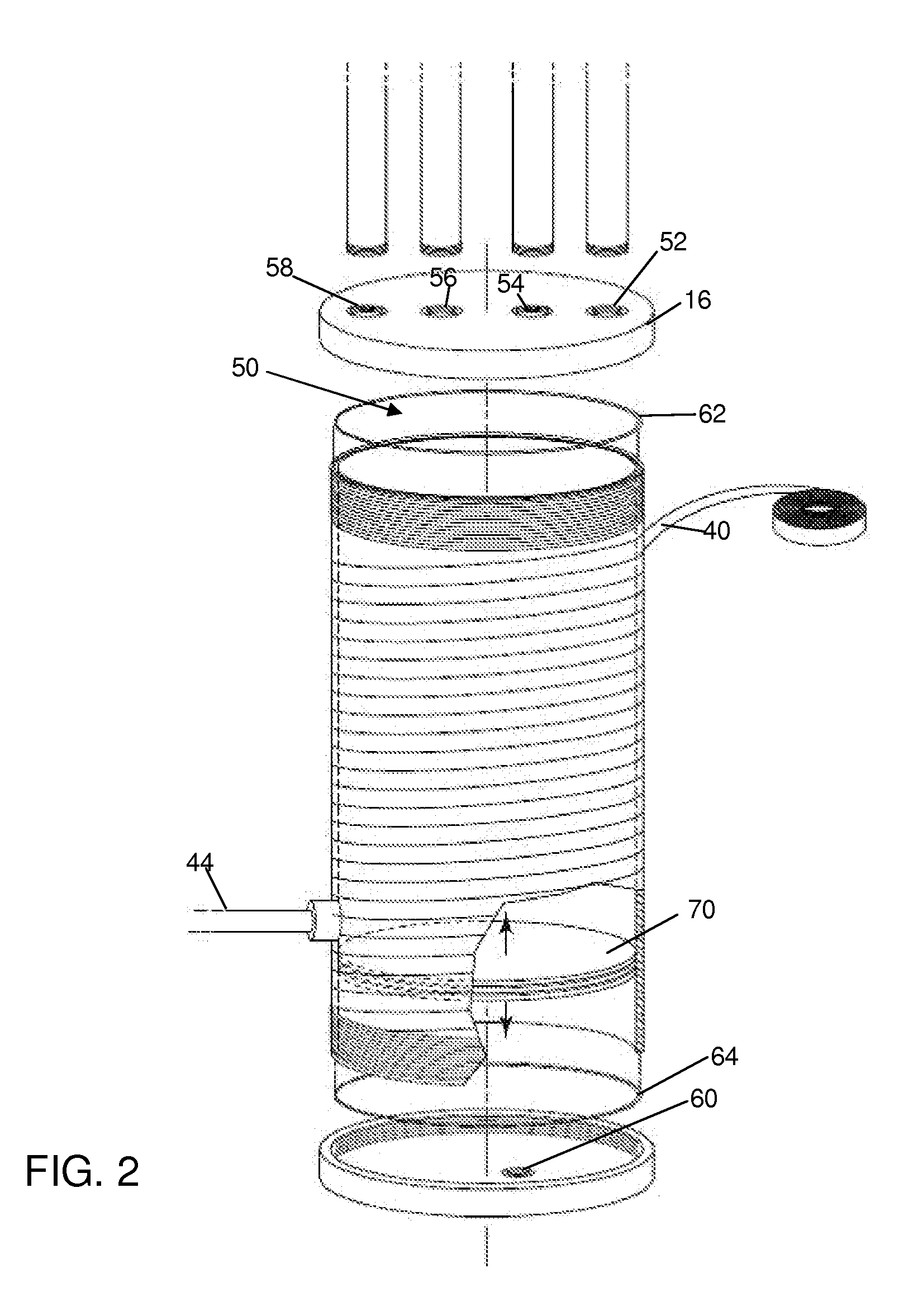
[0029]Referring in general to FIGS. 1-3, an apparatus 10 is illustrated for testing a fracturing fluid used for downhole oil reservoir and / or water shutoff treatments. Apparatus 10 includes a chamber 12 for receiving a sample of fracturing fluid for testing, e.g., from a frac-tank after suitable mixing and prior to downhole introduction. The chamber 12 is in fluid communication with a pressure source 14 via first pressure line 20 passing through a first removable end-cap 16 and a second pressure line 22 passing through a second removable end-cap 18.

[0030]A main pressure valve 24 is provided proximate the outlet 26 of the pressure source 14. In addition, a valve 28 is provided along first pressure line 20 and a valve 30 is provided along second pressure line 22. A fluid-tight piston 70 is closely fit within the chamber 12. The piston is driven by gas from line 22 associated with the pressure source 14. Pressure, e.g., up to about 2000 psi, is applied to the contents of the chamber 12...


PUM


Abstract

An apparatus and process for testing a sample of a hydraulic fracturing fluid is provided. A small quantity of a fracturing fluid sample to be observed and / or tested is placed in a chamber designed with suitable heat and pressure simulation apparatus. With the sample chamber, the efficacy of the fracturing fluid can be ascertained, improper fracturing fluid compositions and / or mixtures, e.g., caused by human error, can be detected, and contamination of the frac-tank can be determined. The overall apparatus is portable and can be transported to the site of the fracturing fluid tank, thereby allowing testing immediately prior to introduction into the well. The samples in the test chamber can be observed for quality control and quality assurance prior to, or during stimulation and water shutoff treatments in the field.

Description

RELATED APPLICATIONS[0001][Not applicable]BACKGROUND OF THE INVENTION[0002]1. Field of the Invention[0003]This invention relates to a portable apparatus for testing and observing chemical interactions of a fluid sample, and a process for testing fracturing fluids commonly used for oil reservoir and / or water shutoff treatments.[0004]2. Description of Related Art[0005]Hydraulic fracturing, including introduction of proppants in subterranean oil-bearing reservoir rock formations, is a well known procedure to stimulate well production. Typically, the fracturing fluid and proppants are mixed in a mobile storage vessel, e.g., a trailer-mounted fluid storage container known as a “frac-tank,” located at the surface near the well site. Chemical additives, including gel polymers and chemical inhibitors, and energizing components such as carbon dioxide and nitrogen gas, are also mixed in the fracturing composition.[0006]After adequate mixing in the frac-tank, the fracturing fluid is pumped via...

Claims


Application Information

Patent Timeline
IPC IPC(8): G01N33/00
CPCG01N2001/1062G01N33/2823
Inventor AL-DHAFEERI, ABDULLAH M.AL-HARITH, ABDULLAH M.AL-FUWAIRES, OMAR A.
Owner SAUDI ARABIAN OIL CO
Learn More