Transfer Device

Inactive Publication Date: 2011-09-29
WITHERSPOON DWIGHT
View PDF4 Cites 3 Cited by
  • Summary
  • Abstract
  • Description
  • Claims
  • Application Information

AI Technical Summary

Benefits of technology

[0013]A number of liners can also be nested in one of the trays for return to the top of the roof, and they can also be hooked to the tray in a nested position. The apparatus preferably does not use any power driven wind-up drum, although it could. Once the tray is released at the rooftop, the cable is preferably oriented so that it needs no operator on the ground. The tray is preferably is automatically tripped, dumping the contents, and automatically brought back to the rooftop. Also, the liner can be filled with debris, then folded up and easily carried by the handles to the roof fixture, and placed in the tray to be carried down to the trash bin, thus replacing the cumbersome tarps. The trays are preferably oriented at an angle so that the carriers can be moved to two separate locations, such as when a pair of receivers such as a pair of light trucks are parked along a street and are receiving sorted materials into each truck.

Problems solved by technology

Roof removal has always been a dirty, difficult and unsafe job.
At times, the dump truck cannot get close to the building making the job twice as difficult and time consuming, as the loaded tarp must be dropped down, and carried out to the dump truck.
While a variety of different mechanisms exist for transporting other types materials, a transfer system of the present invention more particularly suited for roof debris removal is currently lacking.

Method used


Image

  • Transfer Device
  • Transfer Device
  • Transfer Device

Examples


Embodiment Construction

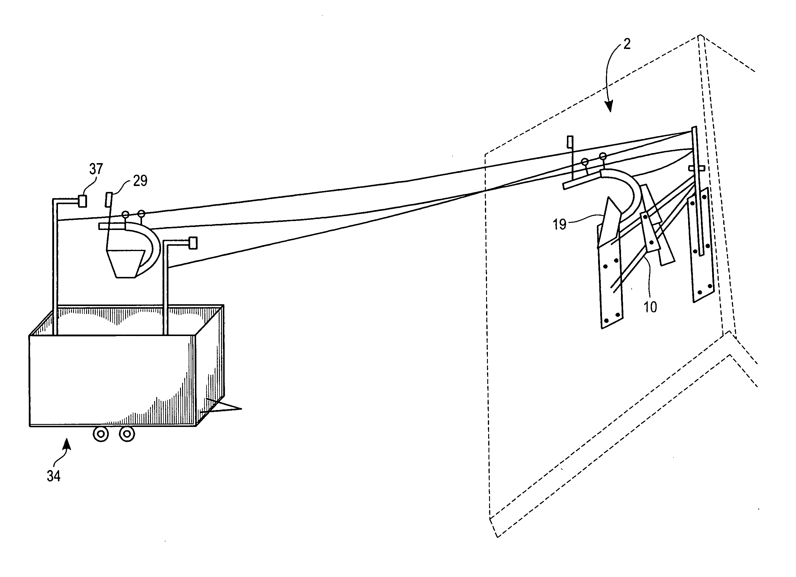
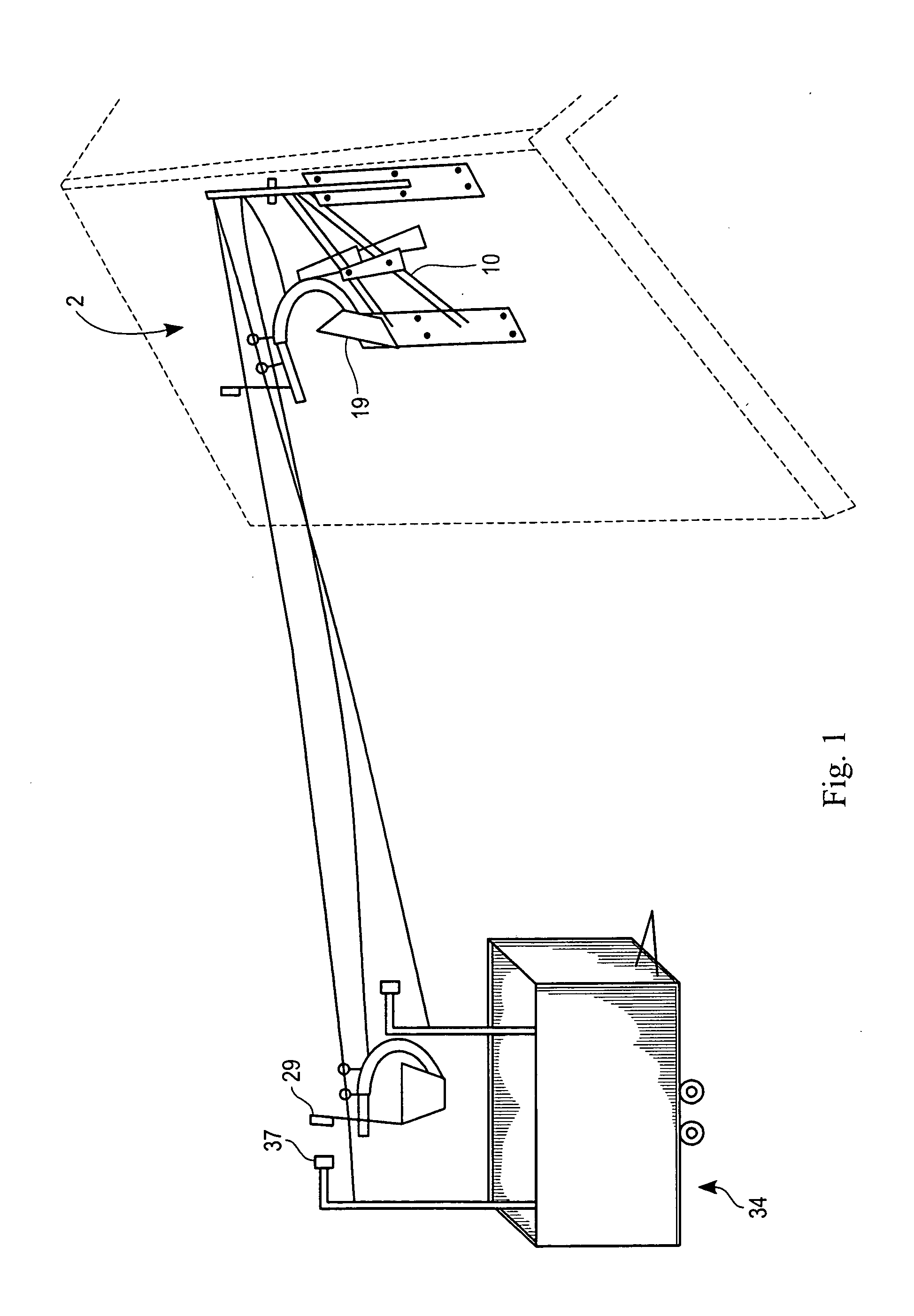
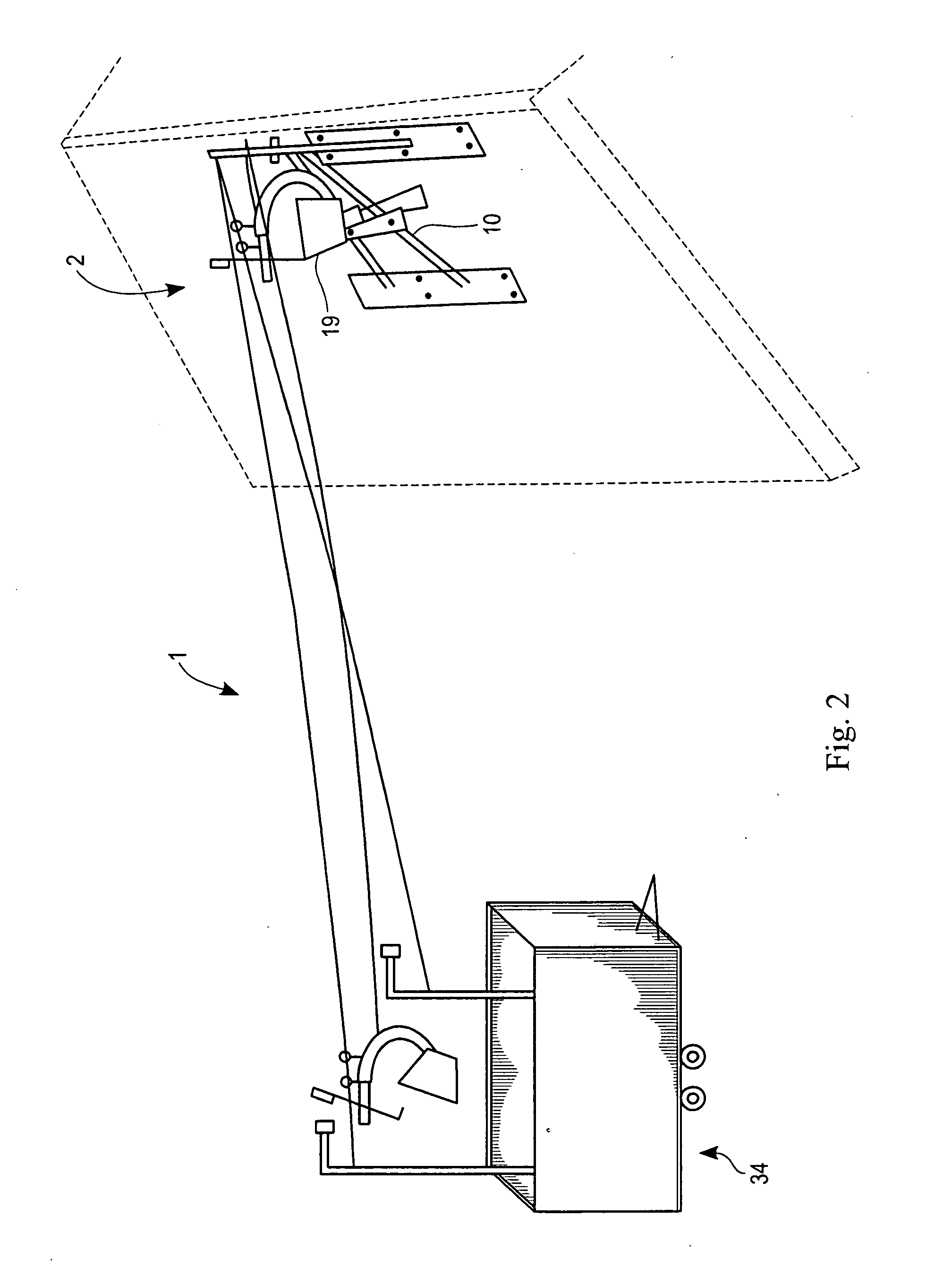
[0070]The transfer device 1 is a device configured and designed to carry roof debris from the top of a roof down to a trash bin 34. The roof fixture 2 is designed to have a sturdy base mounted on a rooftop, such as at a peak of a roof

[0071]The main pole 3 provides a frame to receive an anchoring connection for the support cable 17 and control line 15 at the rooftop. The main pole 3 may be tubing and may comprise of strong, lightweight hard metal. The main pole 3 preferably extends generally vertically from the mount plate 5 which is mounted to the roof such as by nails through nail holes 9. The one or more brace poles 4 can be designed to hold the main pole 3 in a vertical position. The brace pole 4 may comprise of strong, lightweight hard metal. The mount plate 5 is designed to be fastened to the roof deck, while accommodating the main pole 3 and brace pole 4. The mount plate 5 could be made of wood or metal such as aluminum. The swivel bracket 6 is designed for a means of connecti...


PUM


Abstract

A transfer device has a roof fixture adapted to be secured to a roof and protrude upwardly. A first support cable is connected to the roof fixture at a first support cable upper end and a second support cable connected to the roof fixture at a second support cable upper end. A control line has a first segment at a first end and a second segment at a second end. A first carrier is suspended from the first support cable via a first trolley, and the first carrier is connected to the first segment of the control line. The first carrier comprises a tray structure having a first cavity for receiving articles. The first carrier has a tray which is pivotally connected to the first carrier to allow pivotal dumping of the contents from the first tray.

Description

[0001]This application claims priority from Dwight Witherspoon's provisional application Center Ser. No. 61 / 396,182 filed May 24, 2010, the disclosure of which is incorporated herein by reference.FIELD OF THE INVENTION[0002]The present invention is in the field of transfer devices, more specifically for a gravity driven collection device.DISCUSSION OF RELATED ART[0003]A variety of roofing work is only possible when a roof is removed. For example, an old-roof that may no longer be to code may need to be removed. Roof removal has always been a dirty, difficult and unsafe job. Once the old roof has been pried up, it must be carried, usually in a plastic tarp, from the back of the building, over the top and down to the front edge, and then thrown into the trash bin. At times, the dump truck cannot get close to the building making the job twice as difficult and time consuming, as the loaded tarp must be dropped down, and carried out to the dump truck. Also, the debris needs to be distrib...

Claims


Application Information

Patent Timeline
IPC IPC(8): E04G21/14B61B7/00
CPCB61B7/02
Inventor WITHERSPOON, DWIGHT
Owner WITHERSPOON DWIGHT
Why Eureka
Try Eureka