

Multi-Purpose Self-Cleaning Brush
- Summary
- Abstract
- Description
- Claims
- Application Information
AI Technical Summary
Benefits of technology
Problems solved by technology
Method used
Image

Examples
first embodiment
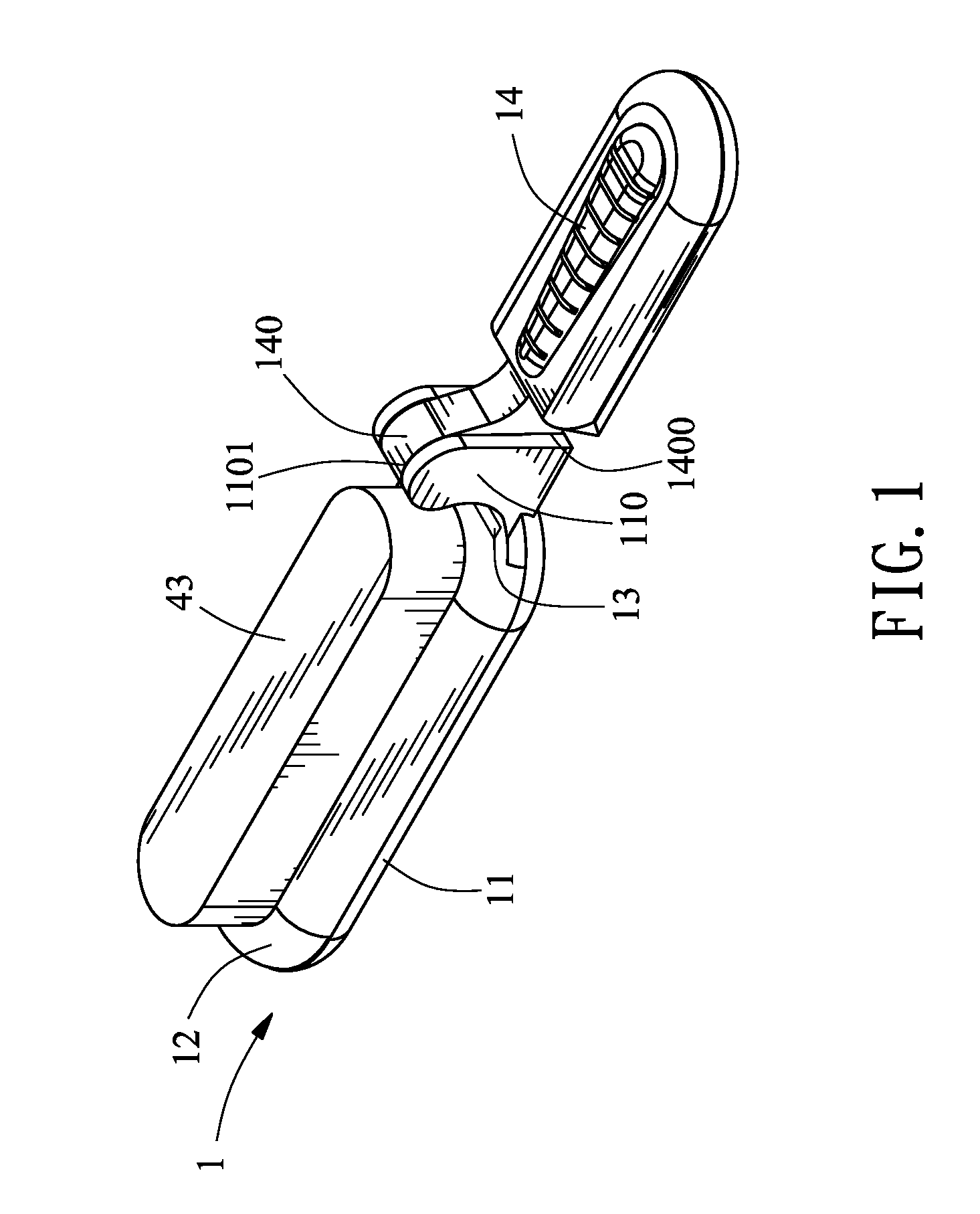
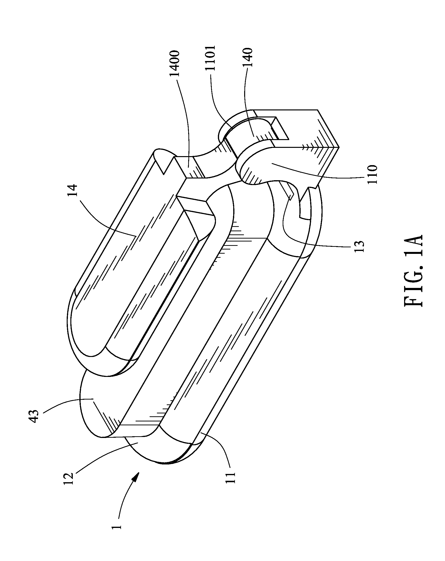
[0086]Referring to FIG. 3, which is a schematic view illustrating the multi-purpose self-cleaning brush being in use according to the present invention. As shown in FIG. 3, when the present invention is in use (also referring to FIG. 1 and FIG. 2), the handgrip 14 folded on top of the base 11 is rotated through the buckle part 140 formed at one side and the handgrip seat 110 having the buckle part 1101 correspondingly installed at one side of the base 11 serving as the shaft, so the handgrip 14 is rotated to one side of the base 11 and the stop part 1400 installed at one side of the handgrip 14 is served to abut against the handgrip seat 110 thereby forming a linear state, so the user is enabled to directly hold the handgrip 14 of the brush body 1, and each bristles 22 of the bristle unit 2 can be served to comb and style the hairs, and the combing and styling action can be omnidirectionally processed; after being used for a period of time and each bristle 22 on the cleaning part 34...
second embodiment
[0090]Referring to FIG. 4B, which is a schematic appearance view illustrating the handgrip not being provided according to the present invention. As shown in FIG. 4B, the base 11 is not installed with the handgrip 14 thereby forming a brush with no handgrip 14, so the user can directly hold the base 11 for utilization, i.e. the base 11 can be directly used as the handgrip 14.
[0091]Referring to FIG. 5, which is a schematic view showing the third embodiment of the present invention. As shown in FIG. 5, the structural configuration of the base 11 and the top cover 12 disclosed in the first embodiment can also be formed as the structural configuration disclosed in the third embodiment, wherein the difference between the first and the third embodiment is that magnetic members 112b, 122b mutually attracting to each other are installed between a base 11b and a top cover 12b, thereby allowing the base 11b and the top cover 12b to be combined through the magnetic members 112b, 122b, so the a...
PUM
 Abstract
Description
Claims
Application Information