Tape measure

Inactive Publication Date: 2007-05-10
BLACK & DECKER INC
View PDF40 Cites 8 Cited by
  • Summary
  • Abstract
  • Description
  • Claims
  • Application Information

AI Technical Summary

Benefits of technology

[0006] The tape measure of the invention consists of a tape blade that may be 1.5 to 2 inches in width and that may extend to 100 feet when fully extended. The blade may be made of steel and have a cross-section shape that maximizes its standout. To accommodate such a large blade the tape measure housing is formed as a hollow annulus having an open central core where the blade is wound about the core of the annular housing. Because th

Problems solved by technology

While increased standout is viewed as a positive feature on tape blades, standout is limited by constraints on the size and weight o

Method used


Image

  • Tape measure
  • Tape measure
  • Tape measure

Examples


Example

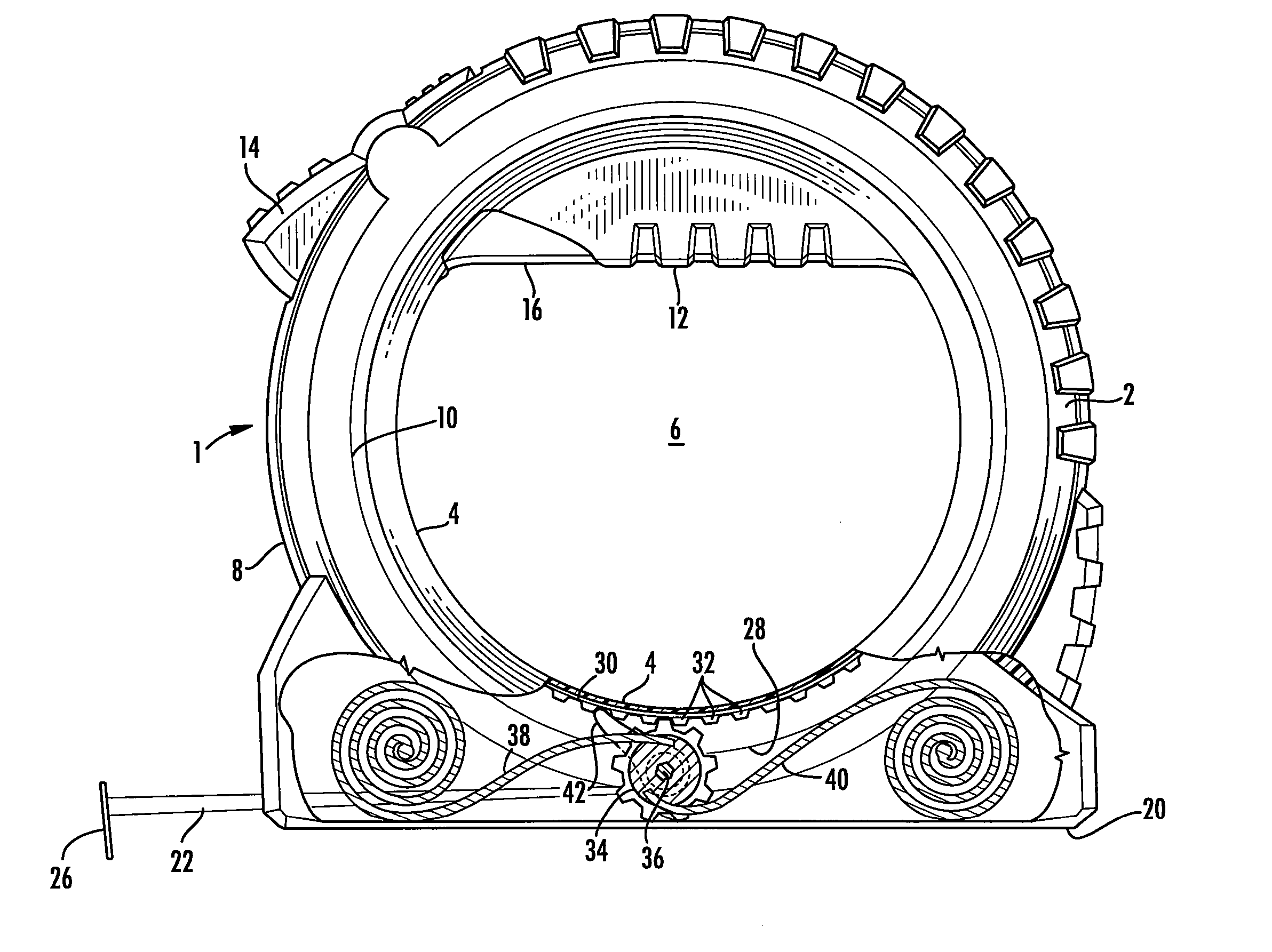
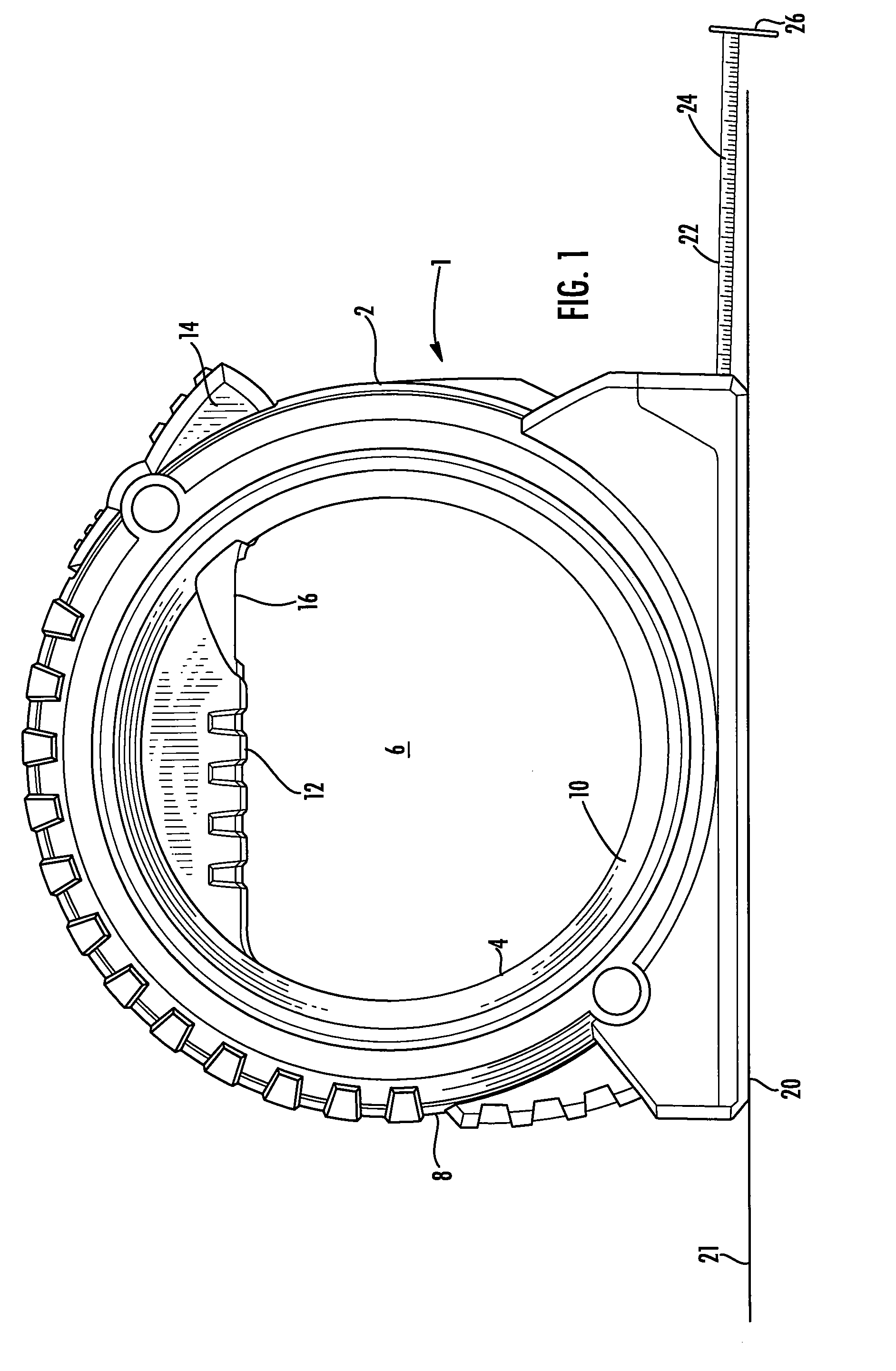
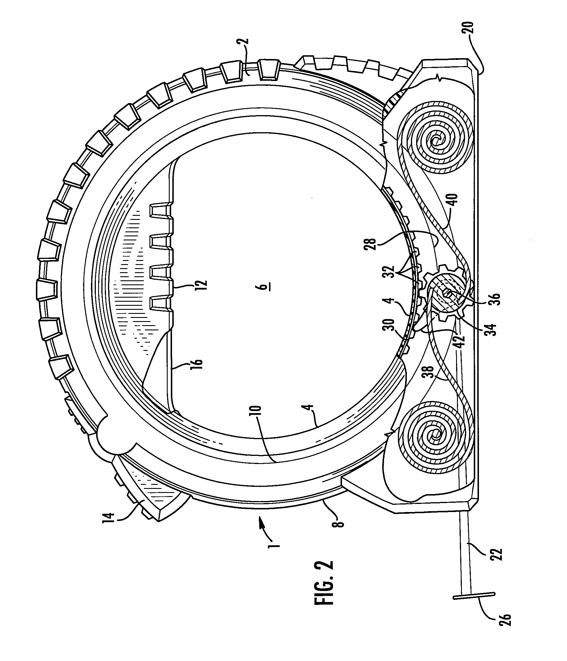
[0010] Referring to FIG. 1 the tape measure of the invention is shown generally at 1 and comprises a housing 2 having an annular shape defined by a generally circular inner wall 4 that defines an internal void 6. The housing 2 has a generally circular outer wall 8 where the outer and inner walls are spaced by side walls 10 a distance such that a user can grip the housing. A handle portion 12 is formed on the housing to facilitate the gripping of the tape measure and a brake lever 14 and rewind lever 16 are located adjacent the handle such that the levers may be manipulated by one hand. It is contemplated that the tape measure will be gripped by an end user extending their fingers through void 6 to grip handle portion 12 much like a suitcase handle. The outer wall 8 is formed with a flat surface 20 such that the tape measure can be placed on a surface 21 to stand upright as shown in FIG. 1.

[0011] The blade 22 extends from the housing through an aperture located near the flat surface...


PUM


Abstract

The tape measure may consist of a relatively large tape blade. To accommodate a large blade the tape measure housing is formed as a hollow annulus having an open central core where the blade is wound about the core of the annular housing. Because the housing has a central opening it can be easily carried in one hand. The device also includes a locking mechanism for locking the tape in an extended position and a rewind mechanism for rewinding the tape back into the housing. The rewind mechanism may comprise a belt drive, opposed springs with a cam lock, a linear spring compressed by a gear drive, a motor driven gear drive, a flat spring and gear drive or a magnetic drive.

Description

CROSS REFERENCE TO RELATED APPLICATIONS [0001] This application claims the benefit of priority under 35 U.S.C. § 119(e) to the filing date of U.S. Provisional Application 60 / 728,173 filed on Oct. 19, 2005, which is incorporated herein by reference in its entirety.BACKGROUND OF THE INVENTION [0002] The invention relates generally to a tape measures and more particularly to a tape measure suitable for use with a large tape blade. [0003] Tape measures as are known consist of a tape blade typically formed of steel, woven fabric or other material that allows the blade to be wound in a housing. The tapes are typically extended from the housing manually and retracted into the housing automatically by a torsion spring that is located inside of a hub around which the tape is wound. A brake may be provided to hold the tape in an extended position and offset the retraction force exerted by the spring. Steel blades are typically formed with an arcuate or other involute cross-section that allows...

Claims


Application Information

Patent Timeline
IPC IPC(8): G01B3/10
CPCG01B3/1005G01B3/1082G01B2003/1028G01B2003/1043G01B2003/1046G01B3/1003G01B3/1043G01B3/1046G01B3/1041
Inventor LEVINE, STEVEN R.WEIR, JAMES ALANWHITNEY, HAMILTON SEAN MICHAELSHUTE, MATTHEW R.BURRY, JAMES M.
Owner BLACK & DECKER INC
Why Eureka
Try Eureka