Hybrid RF/optical communication system with deployable optics and atmosphere compensation system and method

Active Publication Date: 2006-01-12
THE BOEING CO
View PDF15 Cites 6 Cited by
  • Summary
  • Abstract
  • Description
  • Claims
  • Application Information

AI Technical Summary

Benefits of technology

[0007] In the preferred embodiments the wavefront correction system is supported closely adjacent to the antenna aperture of the antenna system. Th

Problems solved by technology

The size and weight of large optical structures (lenses or mirrors, including mounts) suited for optical communications has largely preclu

Method used


Image

  • Hybrid RF/optical communication system with deployable optics and atmosphere compensation system and method
  • Hybrid RF/optical communication system with deployable optics and atmosphere compensation system and method
  • Hybrid RF/optical communication system with deployable optics and atmosphere compensation system and method

Examples


Example

[0013] The following description of the preferred embodiment(s) is merely exemplary in nature and is in no way intended to limit the invention, its application, or uses.

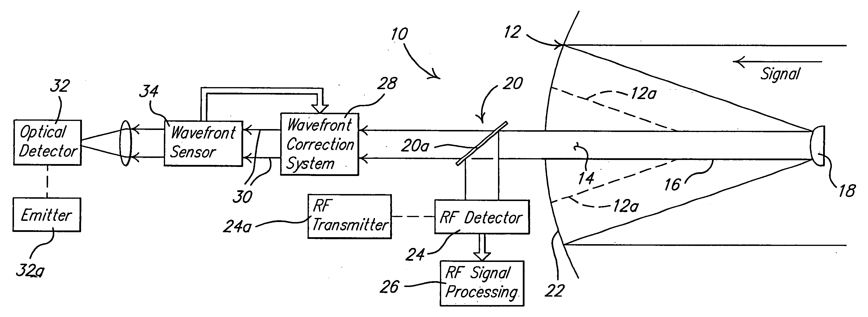
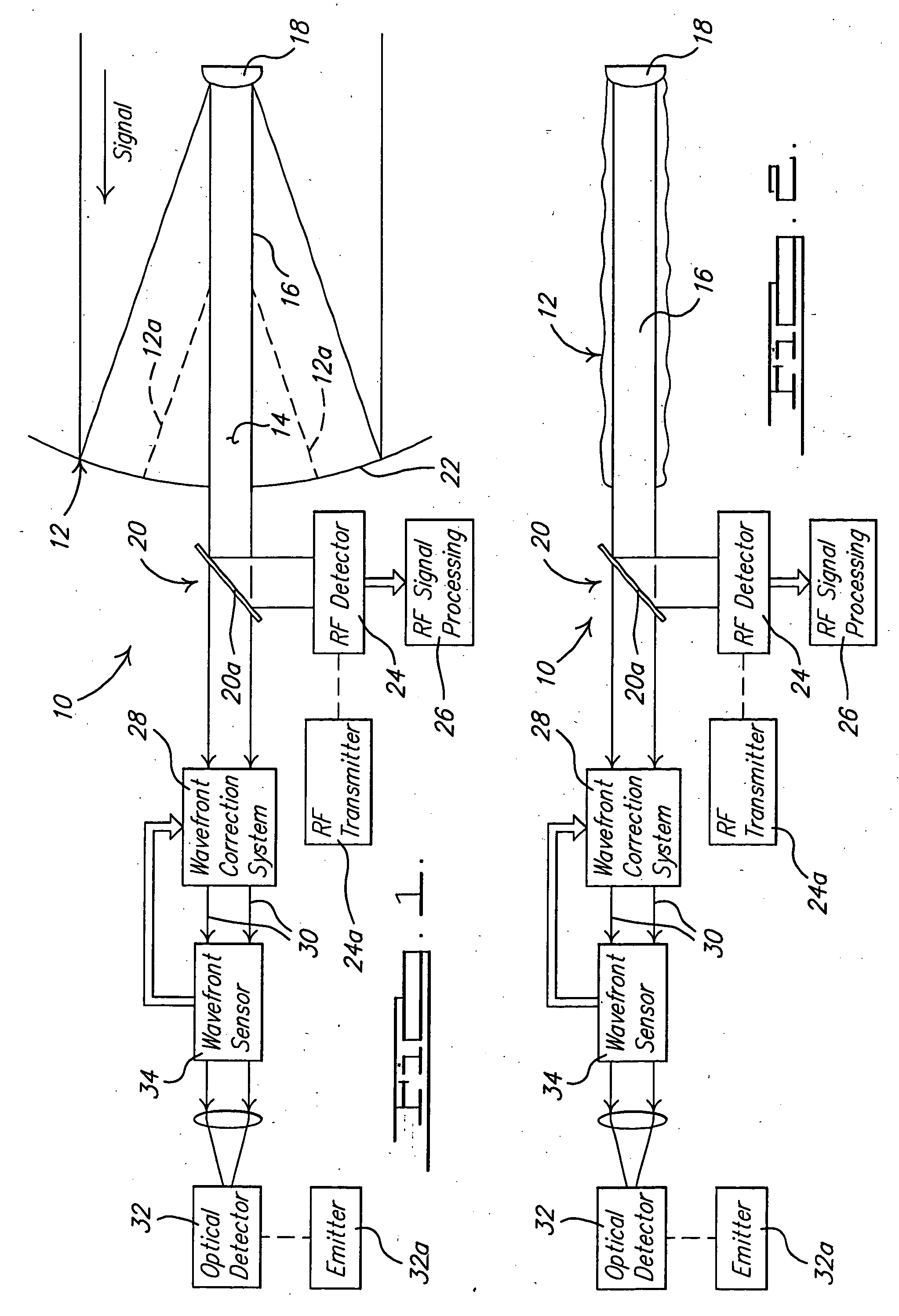
[0014] Referring to FIG. 1, there is shown an antenna system 10 in accordance with a preferred embodiment of the present invention. The antenna system 10 operates to receive both RF and optical radiation via a single antenna aperture 12. In referring to “RF” radiation it is meant electromagnetic wave radiation having a frequency of typically between about 1 GHz and 50 GHz or lower. The antenna aperture 12 is shown in FIG. 1 in its operative position ready for use. FIG. 2 illustrates the system 10 with the antenna aperture 12 in a stowed configuration for transport, making the system 10 much more easy and convenient to carry.

[0015] The antenna aperture 12 includes a reflector 13 made from suitable materials such as metalized mylar or stiff metalized molded plastic. The reflector 13 includes an axial center 14 at whi...


PUM


Abstract

An antenna system for receiving both RF wave and optical wave radiation via a single antenna aperture that may be moved between stowed and deployed configurations as needed. The system includes a wavefront correction system for correcting optical wavefront distortion errors caused by anomalies in the shape of the antenna aperture itself, as well as optical wavefront distortion errors caused by atmospheric perturbations. The optical components used for optical signal conditioning are supported from the antenna aperture and form a compact, unobtrusive means for separating electromagnetic and optical wave signals received by the antenna aperture.

Description

TECHNICAL FIELD OF THE INVENTION [0001] This invention relates to antenna systems, and more particularly to a deployable antenna system able to receive and transmit radio frequency (RF) and optical frequency radiation, and to correct for wavefront distortion in the received optical radiation caused both by geometric anomalies in the antenna aperture itself, as well as wavefront distortion caused by atmospheric factors. BACKGROUND OF THE INVENTION [0002] Optical communications are rapidly becoming the preferred approach for secure, high-bandwidth communications. The size and weight of large optical structures (lenses or mirrors, including mounts) suited for optical communications has largely precluded their mobile, individual use. The optical equipment has not supported RF communications, forcing users to also carry RF equipment, too. [0003] A compact, lightweight, field deployable antenna system of the present invention enables both optical and RF bidirectional communications (trans...

Claims


Application Information

Patent Timeline
IPC IPC(8): H04B10/00
CPCH01Q3/2676H01Q19/191H01Q5/22H04B10/1121H01Q21/30
Inventor WILCKEN, STEPHEN K.SAINT CLAIR, JONATHAN M.
Owner THE BOEING CO
Why Eureka
Try Eureka