Gas burner for domestic cookers

Active Publication Date: 2011-09-29
SABAF SPA
View PDF29 Cites 13 Cited by
  • Summary
  • Abstract
  • Description
  • Claims
  • Application Information

AI Technical Summary

Benefits of technology

[0013]Substantially, according to the invention, immediately upstream of the outflow port of the pilot flame, is disposed, in fluidic connection with such a port, a storage chamber, in its turn placed downstream of one or more inlet port for the fuel mixture, which chamber having the double task of generating a controlled pressure drop of the fuel mixture exiting from the inlets and further of containing a certain volume of fuel mixture accumulating during at least the ignition transitory of the pilot flame and / or the main flames. In this way, during the ignition transitory, but during the regular functioning of the burner too, differently from what happens in the burners of the known art, the storage chamber will operate as a stabilizer of the exit pressure of the fuel mixture feeding the pilot flame from the corresponding outflow port, as well as it will operate as a auxiliary reservoir of the fuel mixture, being able to guarantee the even and regular feeding of such a gas-primary air mixture to the pilot flame, aiding the stability thereof.
[0014]According to the invention, the presence of a storage chamber for the fuel mixture assures an appropriate feeding, relatively to flow rate and pressure, of such a mixture to the outflow port of the pilot flame, at least for the ignition transitory of the burner, and thereby allows to stabilize the pilot flame combustion, and therefore the main flames.
[0015]The storage chamber thus performs the function of regulating the flow pressure, and therefore the flow rate and flow speed of the exiting fuel mixture, preventing the local instantaneous changes of the outer pressure, at the outflow port of the pilot flame of the burner, from involving irregularities in the pilot flame distribution, with a consequent difficult and irregular ignition and / or operation of the burner.

Problems solved by technology

The storage chamber thus performs the function of regulating the flow pressure, and therefore the flow rate and flow speed of the exiting fuel mixture, preventing the local instantaneous changes of the outer pressure, at the outflow port of the pilot flame of the burner, from involving irregularities in the pilot flame distribution, with a consequent difficult and irregular ignition and / or operation of the burner.

Method used


Image

  • Gas burner for domestic cookers
  • Gas burner for domestic cookers
  • Gas burner for domestic cookers

Examples


Embodiment Construction

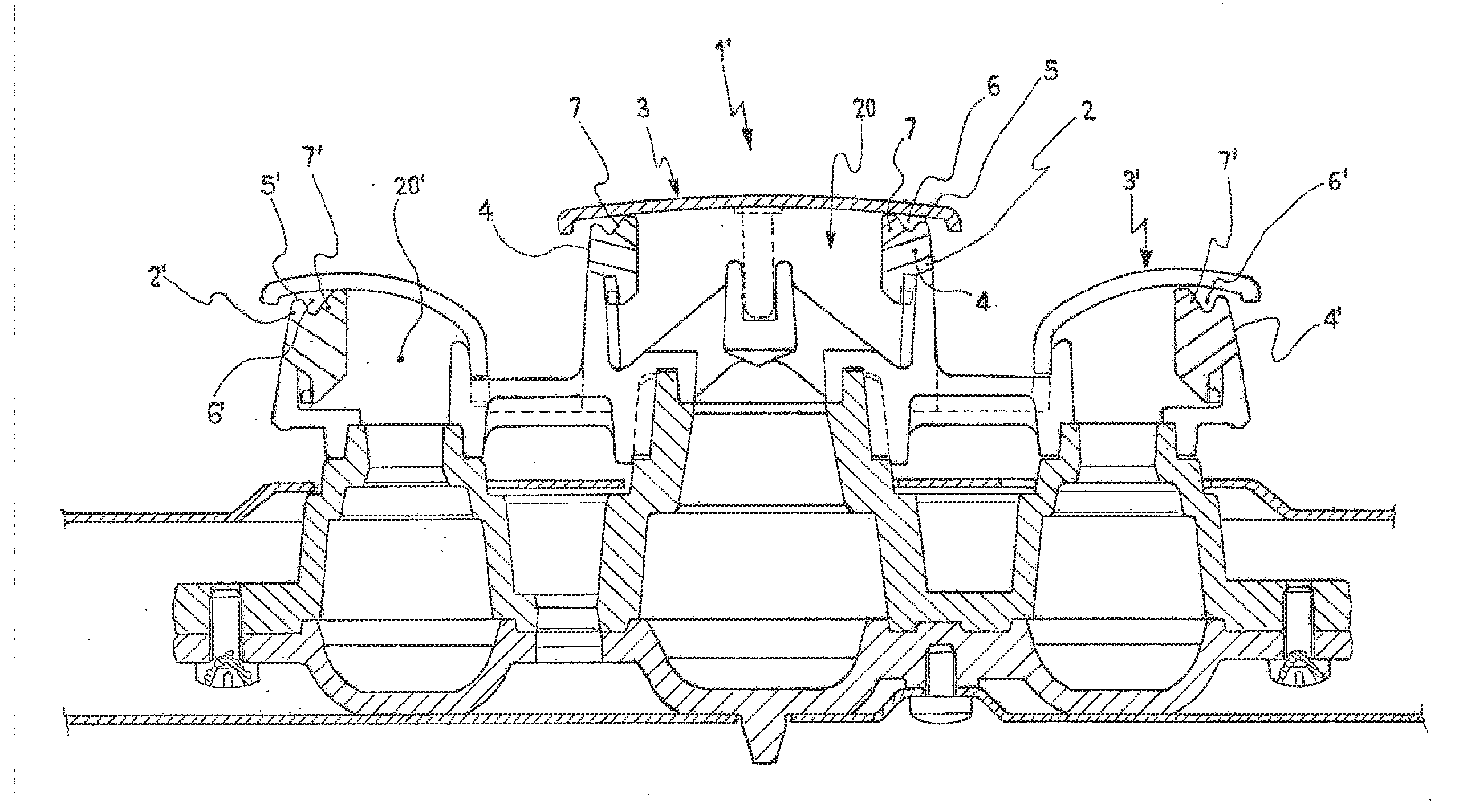
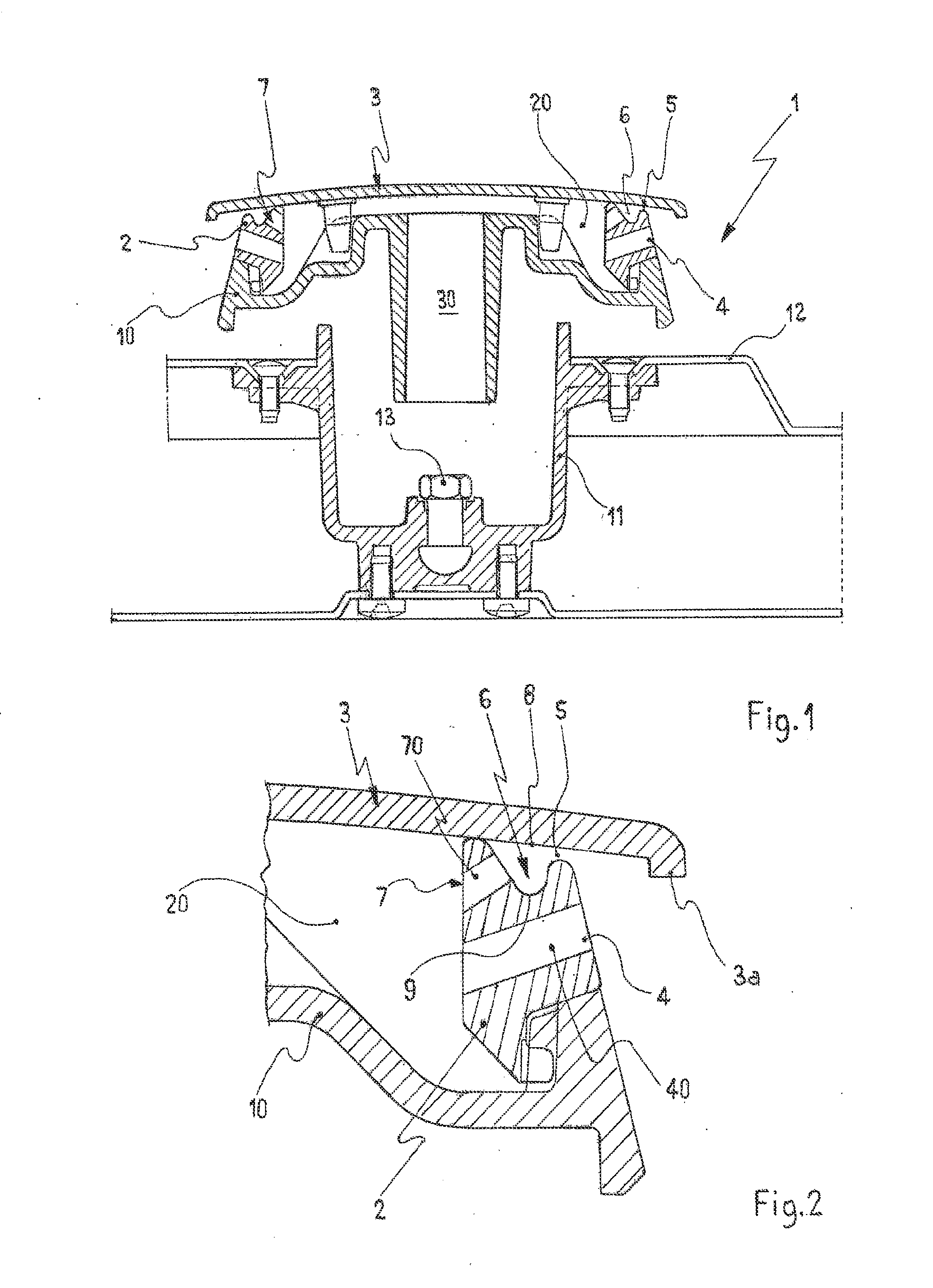
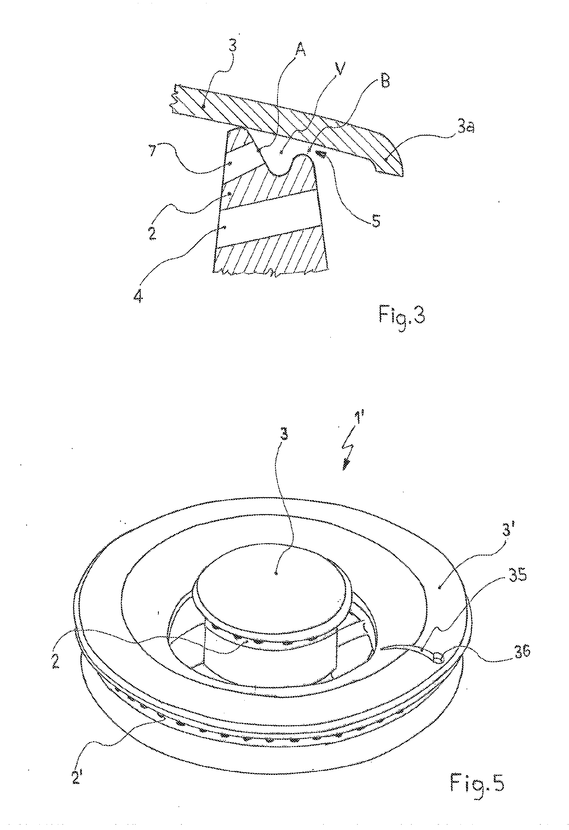
[0028]Referring particularly to such figures, with 1 is shown a burner according to the present invention.

[0029]The burner 1 for gas cooker, according to a particular aspect of the invention, is provided with a flame spreader 2 and a corresponding lid 3, having the complementary shape of the upper surface of the flame spreader 2, the flame spreader 2 and the lid 3 defining, with a beneath body 10 of the burner 1, a transit chamber 20 for a gas-primary air fuel mixture. The flame spreader 2 comprises, in its turn, a plurality of radial outlets 4 for feeding with a gas-primary air fuel mixture a plurality of main flames, and an outlet port 5, placed over the afore said plurality of outlets 4, adapted for feeding a pilot flame with such a fuel mixture. The outlets 4 are obtained by a plurality of through holes 40 passing through the flame spreader 2.

[0030]The flame spreader 2 is engaged, according to the known art, with the body 10 of the burner 1, the body 10 comprising at least part ...


PUM


Abstract

Burner (1) for gas cookers, of the type comprising at least one flame spreader (2) and at least a corresponding lid (3) adapted to define at least partially a transit chamber (20) for a gas-primary air fuel mixture, said at least one flame spreader (2) comprising at least a plurality of radial outlets (4) to feed a plurality of main flames with said fuel mixture, and at least one outflow port (5), placed over said plurality of radial outlets (4), to feed with said fuel mixture at least one pilot flame, said at least one outflow port (5) being shaped to direct said at least one pilot flame towards said at least one plurality of radial outlets (4). The burner further comprises at least one storage chamber (6) for the fuel mixture for said at least one pilot flame, placed nearby and in fluidic connection with said at least one outflow port (5), said storage chamber (6) being fed by one or more inlets (7) disposed in fluidic communication with said transit chamber (20) for the fuel mixture.

Description

FIELD OF THE INVENTION[0001]The present invention refers to a burner for cookers fed by a gas-air fuel mixture.BACKGROUND ART[0002]Particularly, the present invention refers to a type of burner wherein the outflow port, or ports, for feeding the pilot flame with a gas-primary air mixture is disposed, or are disposed, over the radial outlets adapted to feed the main flames with such a gas-primary air mixture. Such an outflow port is particularly shaped to direct the pilot flame towards the outlets of the main flames, so as to allow the ignition of the latter.[0003]Such a burner, responding to a particular normative prescription of some countries, further provides that the outflow port for the pilot flame and the radial outlets for the main flames are realized, at least partially, in the so-called flame spreader, that is, in its turn, closed by a top lid.[0004]It has to be observed that with “flame spreader” is usually meant an annular element provided with, at least partially on its ...

Claims


Application Information

Patent Timeline
IPC IPC(8): F23D14/06F24C3/00F23D14/26
CPCF23D14/06F23D2900/14062F23D2207/00F23D14/58F24C3/08
Inventor BETTINZOLI, ANGELO
Owner SABAF SPA
Why Eureka
Try Eureka