Internal-Combustion-Engine Control Device and Internal-Combustion-Engine Control Method

a control device and combustion engine technology, applied in the direction of electric control, ignition automatic control, combustion air/fuel air treatment, etc., can solve the problems of low efficiency of spark ignition engine, unstable combustion, low efficiency of compression ignition engine, etc., to reduce the effect of nox emissions, high efficiency, and stable combustion

Active Publication Date: 2020-09-17
HITACHI ASTEMO LTD
View PDF0 Cites 1 Cited by
  • Summary
  • Abstract
  • Description
  • Claims
  • Application Information

AI Technical Summary

Benefits of technology

[0012]According to the invention, it is possible to stabilize combustion and suppress NOx emissions without unnecessarily increasing the mounting load on the ECU, and realize a control device of a highly efficient internal combustion engine and a control method for the internal combustion engine.
[0013]Objects, configurations, and effects besides the above description will be apparent through the explanation on the following embodiments.

Problems solved by technology

A spark ignition engine widely used in automobiles has a problem that its efficiency is lower than that of a compression ignition engine because a low load pumping loss and a need to burn an air-fuel mixture at a theoretical mixture ratio are required.
However, the super-lean combustion has a problem that the combustion becomes unstable when the excess air ratio becomes larger than a predetermined value, and NOx is discharged when the excess air ratio becomes smaller than a predetermined value.

Method used


Image

  • Internal-Combustion-Engine Control Device and Internal-Combustion-Engine Control Method
  • Internal-Combustion-Engine Control Device and Internal-Combustion-Engine Control Method
  • Internal-Combustion-Engine Control Device and Internal-Combustion-Engine Control Method

Examples


first embodiment

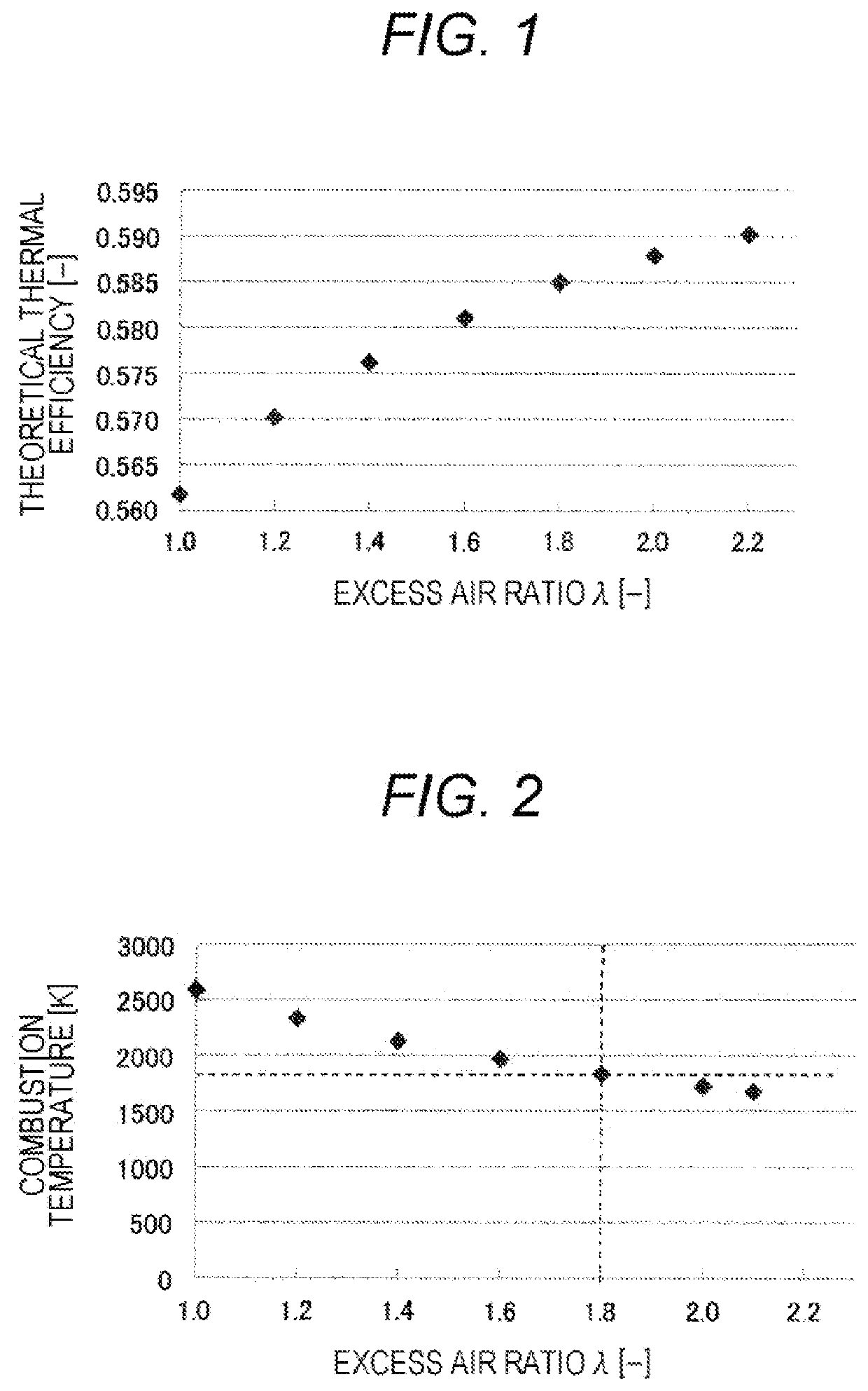
[0029]First, characteristics of a lean-burn internal combustion engine (lean burn engine) will be described with reference to FIGS. 1 and 2. FIGS. 1 and 2 illustrate theoretical values of the thermal efficiency and the combustion temperature with respect to an excess air ratio (hereinafter, also referred to as “λ”) when the Otto cycle is set as a theoretical cycle.

[0030]As illustrated in FIGS. 1 and 2, in the lean burn engine, as the excess air ratio λ increases, the specific heat ratio of the working fluid (air-fuel mixture) increases, thereby improving the theoretical thermal efficiency and increasing, and the combustion temperature drops. Normally, when the combustion temperature is 1800 K or lower, NOx is theoretically not emitted. Therefore, it is understood that, when the excess air ratio λ is 1.8 or higher, both high thermal efficiency and low NOx are compatible.

[0031]On the other hand, as the excess air ratio λ increases, the laminar combustion velocity decreases, and there ...

second embodiment

[0064]A control device and a control method for an internal combustion engine according to a second embodiment will be described with reference to FIGS. 8 to 13.

[0065]In the lean combustion in which the excess air ratio λ is close to 2 as in the first embodiment, it is difficult to achieve a wide rotation speed and a wide torque range because the mountability of auxiliary devices such as a supercharger is restricted. FIG. 8 illustrates the operation zone of lean combustion where the excess air ratio λ is around 2.

[0066]At low loads, it is difficult to realize lean combustion due to the low temperature of the air-fuel mixture at the time of ignition. At high loads, auxiliary equipment such as a turbo is required. Therefore, it can be said that the first embodiment for realizing the lean combustion is suitable for operation at a medium load (operation zone (region) H). For this reason, it is necessary to perform combustion using EGR (Exhaust Gas Recirculation) at low load and high loa...

third embodiment

[0091]A control method for an internal combustion engine according to a third embodiment will be described with reference to FIG. 14. FIG. 14 is a flowchart illustrating a control method for each combustion zone (region) illustrated in FIG. 8.

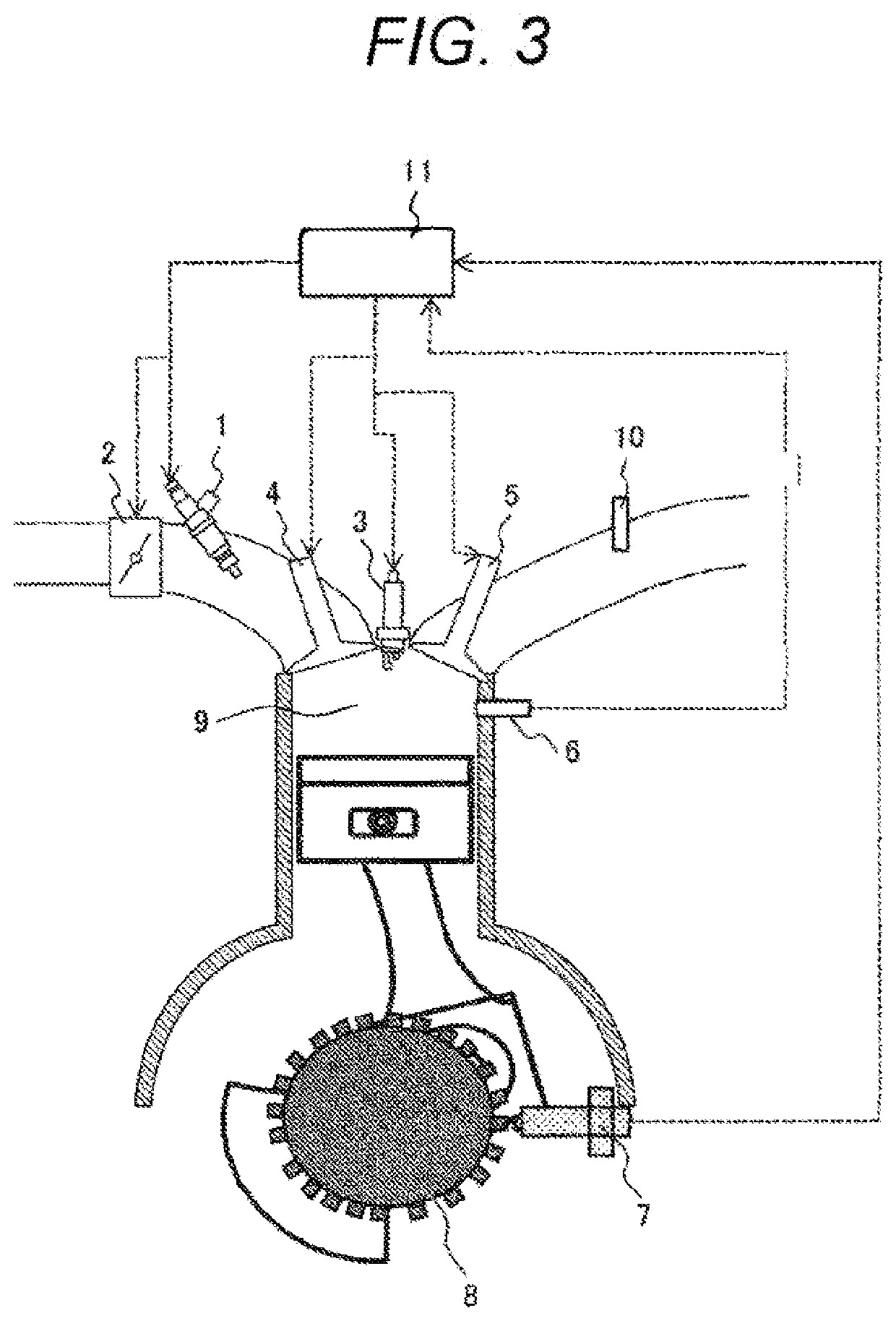
[0092]First, in Step S101, the rotation speed of the engine is measured, and the torque is estimated. The rotation speed is measured by a rotation sensor (crank angle sensor) 7 of the crankshaft 8. The torque is estimated from any of the intake air amount, fuel amount, thermal efficiency, and accelerator opening.

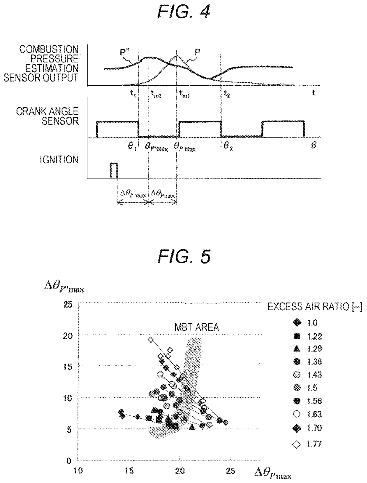
[0093]Next, in Step S102, ΔθPmax and Δθ-P″max are calculated based on the measurement values of the combustion pressure estimation sensor 6.

[0094]Thereafter, in Step S103, the combustion zone (region) determination illustrated in FIG. 8 is performed. When the combustion zone (region) is G or I, since the combustion is an EGR rate control with the excess air ratio λ=1, the map of the EGR rate with ΔθPmax and ΔθP″max as axes and the MBT i...


PUM


Abstract

Provided is a control device and a control method of a high-efficiency internal combustion engine capable of stabilizing combustion and suppressing NOx emissions without unnecessarily increasing a mounting load on an ECU. Therefore, the control device of the internal combustion engine for controlling the internal combustion engine includes an ignition plug that ignites an air-fuel mixture of fuel and air in the combustion chamber, a combustion pressure estimation sensor that detects a combustion pressure in the combustion chamber, and a crank angle sensor that detects a crank angle of a crankshaft. An MBT region is set based on an ignition delay period from an ignition timing of the ignition plug calculated from a detection value of the combustion pressure estimation sensor and a detection value of the crank angle sensor to a combustion start timing in the combustion chamber, and a combustion period from the combustion start timing to a set amount combustion end timing when a set amount of combustion ends. An ignition timing of the ignition plug is controlled so as to fall within the set MBT region.

Description

TECHNICAL FIELD[0001]The present invention relates to control of an engine system for a vehicle, and more particularly to a technique effective for improving the efficiency of an engine system.BACKGROUND ART[0002]In order to respond to the introduction of CO2 regulations and RDE regulations (Real Driving Emission) for automobiles, high efficiency of engines is required. A spark ignition engine widely used in automobiles has a problem that its efficiency is lower than that of a compression ignition engine because a low load pumping loss and a need to burn an air-fuel mixture at a theoretical mixture ratio are required.[0003]Lean combustion with air or inert gas in a spark ignition engine is a means for increasing the specific heat ratio of an air-fuel mixture, improving theoretical thermal efficiency, and reducing pumping loss at low loads. Therefore, a significant improve in thermal efficiency can be realized. In particular, in super-lean combustion with an excess air ratio higher t...

Claims


Application Information

Patent Timeline
Patent Type & Authority Applications(United States)
IPC IPC(8): F02P5/06F02D41/00F02M61/14F02D41/32F02M26/13F02M35/10
CPCF02P5/06F02D41/009F02M35/10222F02D41/0002F02D2200/024F02M61/145F02M26/13F02D41/32Y02T10/40F02D35/028F02D35/023F02D41/1475F02D41/005F02P5/153F02P5/1516F02M26/33F02M2026/009F02D37/02
Inventor SHIMADA, ATSUSHIAONO, TOSHIHIROSARUWATARI, MASAYUKI
Owner HITACHI ASTEMO LTD
Why Eureka
Try Eureka