Valve timing control apparatus for an internal combustion engine

Inactive Publication Date: 2000-08-29
DENSO CORP
View PDF9 Cites 19 Cited by
  • Summary
  • Abstract
  • Description
  • Claims
  • Application Information

AI Technical Summary

Benefits of technology

In view of the problems encountered in the prior art, an object of the present invention is to provide a valve timing control apparatus for an internal combustion engine capable of stabilizing the combustion even in a lean burn control mode and improving the power output characteristics.

Problems solved by technology

However, undesirable change of the valve timing of the intake or exhaust valve leads to unstable combustion during a lean bum control mode.
The increased overlap between the intake and exhaust valve opening periods possibly increases a residual exhaust gas amount remaining in the combustion chamber.
This greatly worsens the emission and the drivability.

Method used


Image

  • Valve timing control apparatus for an internal combustion engine
  • Valve timing control apparatus for an internal combustion engine
  • Valve timing control apparatus for an internal combustion engine

Examples


first embodiment

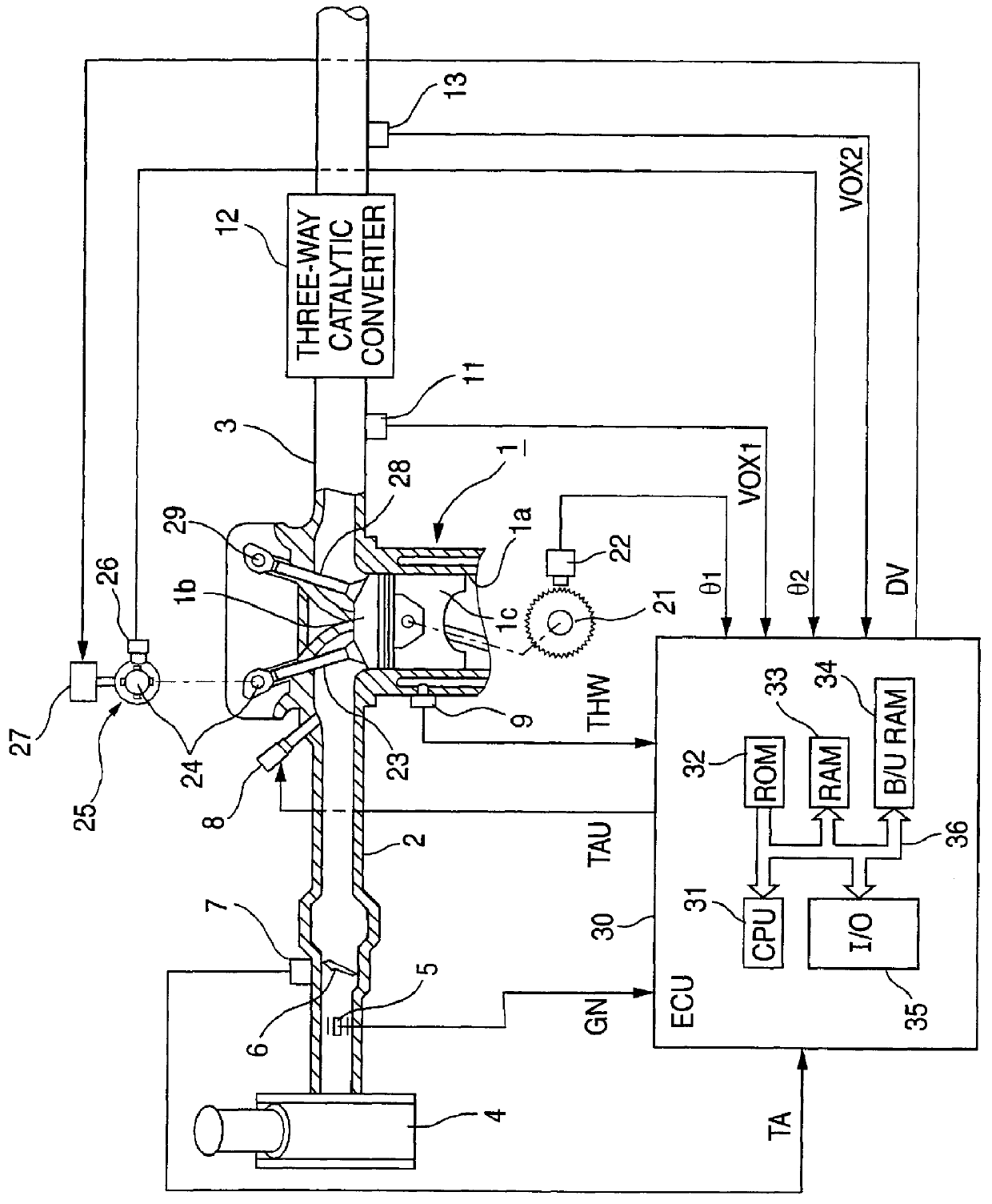
FIG. 1 is a double overhead cam type internal combustion engine equipped with a valve timing control apparatus and related actuating and sensing devices in accordance with a first embodiment of the present invention.

An internal combustion engine 1 comprises a plurality of cylinders 1a respectively connected to an intake passage 2 and an exhaust passage 3. An air cleaner 4 is provided at an upstream side of the intake passage 2. An air flow meter 5 detects an amount of air introduced through the air cleaner 4. A throttle valve 6, provided downstream of the air flow meter 5, is rotatable about its shaft supported at a wall of the intake passage 2. An intake air amount is increased or decreased by opening or closing the throttle valve 6. A throttle sensor 7 detects an opening degree of the throttle valve 6. A downstream side of the intake passage is divided into a plurality of independent passages exclusively communicating with the corresponding cylinders 1a. Each independent passage i...

second embodiment

FIG. 12 is a flowchart showing a processing procedure performed in the CPU 31 of the ECU 30 for setting the fuel injection amount in accordance with a second embodiment of the present invention. The CPU 31 repetitively performs the fuel injection amount setting routine shown in FIG. 12 every 360 degrees [.degree. CA] in synchronism with the rotation of the internal combustion engine 1. FIG. 13 is a map showing a correction factor VTTc corresponding to the target relative rotational angle VTT [.degree. CA]. Like the first embodiment, the second embodiment is realized by using the valve timing control apparatus and the actuating and sensing devices shown in FIG. 1.

In a step S501 of FIG. 12, the CPU 31 reads various sensor signals including the engine speed NE and the intake air amount GN. Next, in a step S502, the CPU 31 calculates a fundamental fuel injection amount Tp based on the various sensor signals read in the step S501. Then, in a step S503, the CPU 31 makes a judgement as to ...

third embodiment

FIG. 19 is a double overhead cam type internal combustion engine equipped with a valve timing control apparatus and related actuating and sensing devices in accordance with a third embodiment of the present invention. According to the third embodiment, a NOx catalytic converter 14 for exclusively purifying nitrogen oxides (NOx) is disposed downstream of the oxygen sensor 13 in the exhaust passage 3 in addition to the arrangement of the first embodiment.

FIG. 20 is a flowchart showing a processing procedure performed in the CPU 31 of the ECU 30 for calculating the control duty with reference to maps of FIGS. 21A and 21B as well as the maps (graphs) of FIGS. 5 and 6 in accordance with the third embodiment of the present invention. FIGS. 21A and 21B are the maps used for calculating the target relative rotational angles VTT.alpha. and VVT.beta. [.degree. CA] based on the engine speed NE [rpm] and the intake air amount GN [g / rev]. The CPU 31 repetitively performs the control duty calcula...


PUM


Abstract

An ECU calculates an actual relative rotational angle in a VVT based on a crank angle signal sent from a crank position sensor and a cam angle signal sent from a cam position sensor. Furthermore, the ECU calculates a fundamental target relative rotational angle based on engine operating conditions. The fundamental target relative rotational angle is corrected by a factor responsive to the change of the air-fuel ratio. Thus, a control rotational angle fed to the VVT varies in accordance with the change of the air-fuel ratio so as to stabilize the combustion and improve the power output characteristics.

Description

BACKGROUND OF THE INVENTIONThe present invention relates to a valve timing control apparatus for an internal combustion engine comprising a variable valve timing control mechanism capable of optimizing an open or close timing of at least one of intake and exhaust valves in accordance with engine operating conditions, and an air-fuel control device capable of varying an air-fuel ratio of gas mixture introduced into a combustion chamber of the internal combustion engine.Unexamined Japanese Patent Application No. Kokai 7-91280, published in 1995, discloses a valve timing control apparatus for an internal combustion engine including a hydraulically controlled variable valve timing control mechanism wherein a control amount is adjustable in accordance with oil nature to improve drivability. Japanese Patent No. 7-68921, published in 1995, discloses another hydraulically controlled variable valve timing control mechanism wherein a control amount is variable to stabilize an idle operating c...

Claims


Application Information

Patent Timeline
IPC IPC(8): F02D41/14F02D41/34F01L1/34F02D13/02F02D45/00F02D41/04
CPCF01L1/34F02D13/0238F02D13/0261F02D41/009F02D41/1441F02D41/1479F02D41/1486F01L2201/00F02D41/1456F02D41/187F02D2041/001Y02T10/18Y02T10/12
Inventor MORIKAWA, JUNYAISOBE, DAIJI
Owner DENSO CORP
Why Eureka
Try Eureka