
Adaptive antenna neutralization network

a technology of neutralization network and adaptive antenna, applied in the direction of antenna coupling, antenna details, antennas, etc., can solve the problems of significant risk, degrade the performance of both transmission and reception, and the antenna will couple with each other

Active Publication Date: 2011-09-29
QORVO US INC
View PDF9 Cites 106 Cited by
  • Summary
  • Abstract
  • Description
  • Claims
  • Application Information

AI Technical Summary

Benefits of technology

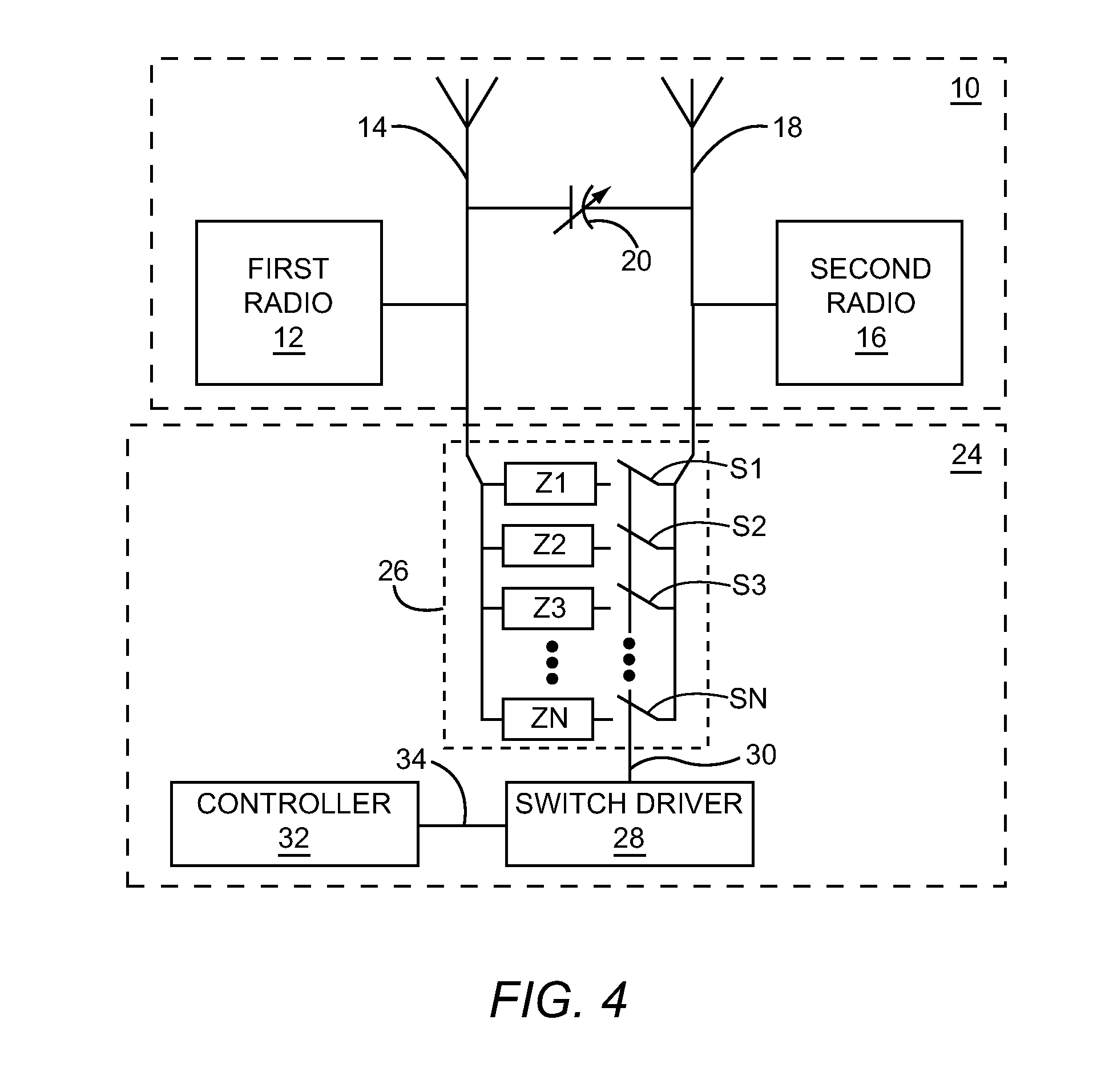
[0006]The controller may include factory calibration settings that are associated with predictable changes in antenna coupling environments. In this way, when a predictable antenna coupling change occurs, the controller can quickly respond by commanding the switch driver to switch in or out appropriate ones of the reactive elements such that antenna coupling is neutralized or at least minimized. The AANN also includes a sensor for detecting the coupling state between the first antenna and the second antenna during unpredictable changes in the antenna coupling environment. Detection of the coupling state is fed back to the controller over a feedback path. In this way, the controller can compare the coupling state measured by the sensor with a desired minimal antenna coupling state and command the switch driver to switch in or switch out appropriate ones of the reactive elements such that antenna coupling can be neutralized or at least minimized.

Problems solved by technology

Thus, there is a significant risk that the antennas will couple with each other either capacitively or inductively.
Such antenna coupling has the potential to degrade the performance of both transmissions and receptions during operation of a mobile terminal having multiple antennas.
There have been prior art attempts to neutralize antenna coupling, but these prior art attempts have not been completely successful in handling antenna coupling.
These unsuccessful attempts suffer from variability in antenna coupling environments.
For example, a fluctuating voltage standing wave ratio (VSWR) caused by repositioning of a mobile terminal in relationship to a user's body cannot be accommodated by prior art antenna neutralization schemes.

Method used


Image

  • Adaptive antenna neutralization network
  • Adaptive antenna neutralization network
  • Adaptive antenna neutralization network

Examples


Embodiment Construction

[0030]The embodiments set forth below represent the necessary information to enable those skilled in the art to practice the embodiments and illustrate the best mode of practicing the embodiments. Upon reading the following description in light of the accompanying drawing figures, those skilled in the art will understand the concepts of the disclosure and will recognize applications of these concepts not particularly addressed herein. It should be understood that these concepts and applications fall within the scope of the disclosure and the accompanying claims.

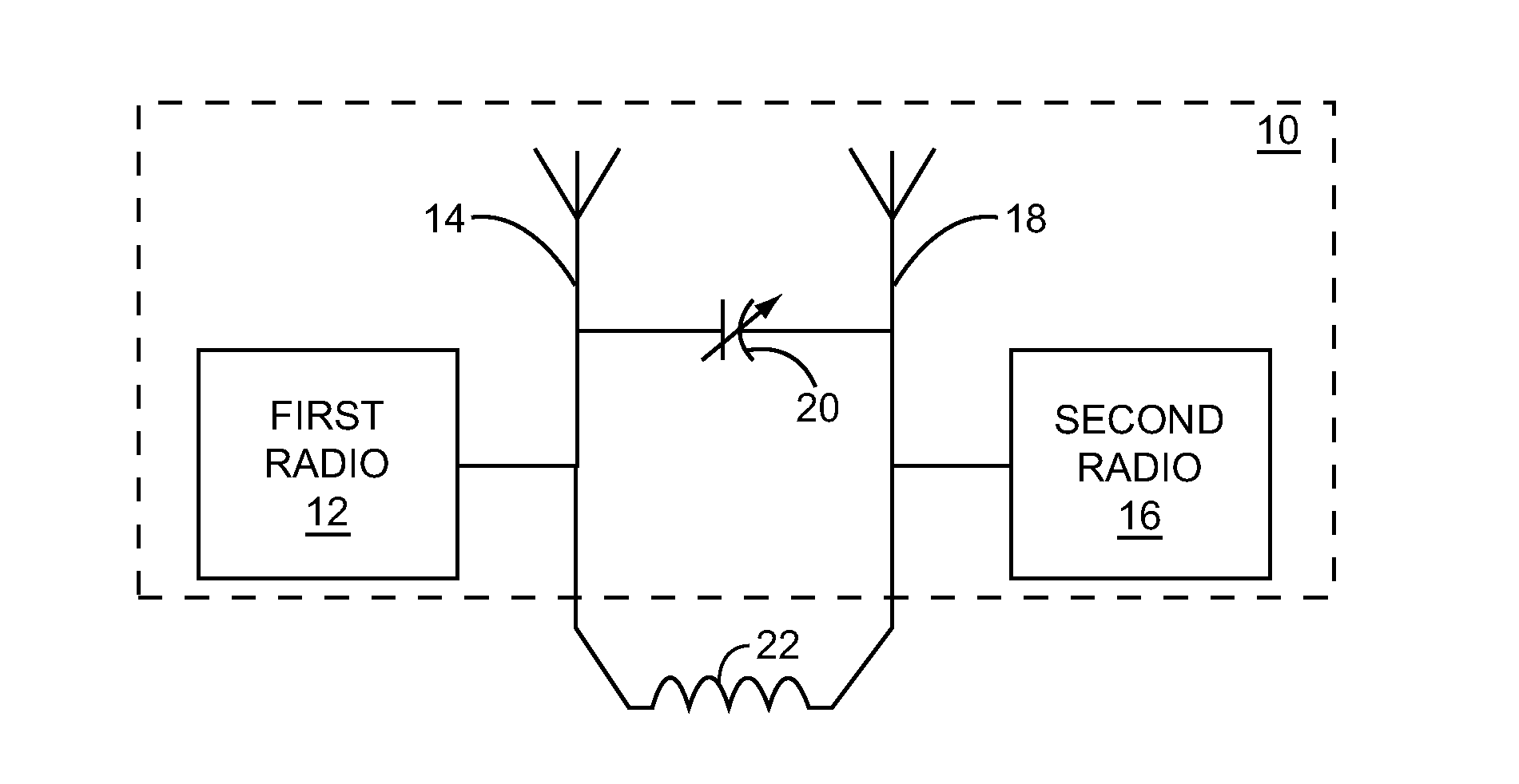
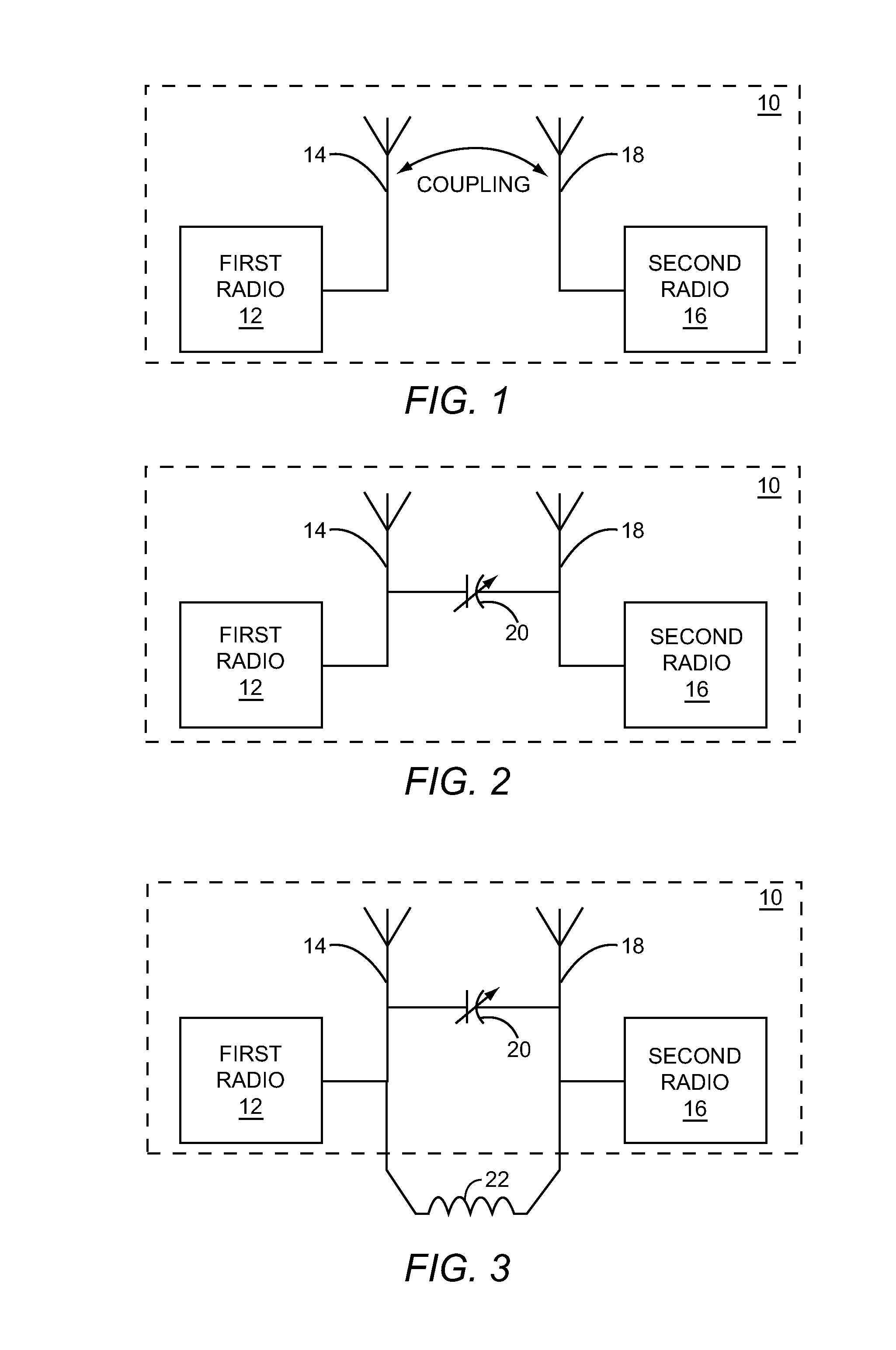
[0031]FIG. 1 is an illustration of a front end radio architecture (FERA) 10 having a first radio 12 with a first antenna 14 and a second radio 16 with a second antenna 18 that experiences undesirable antenna coupling. The coupling between the first antenna 14 and the second antenna 18 may be capacitive or inductive depending on the structure of the FERA 10 along with the relative positioning between the first antenna 14 and t...


PUM


Abstract

An adaptive antenna neutralization network (AANN) for neutralizing coupling between a first antenna and a second antenna of a mobile terminal is disclosed. The AANN includes an array of reactive branches. Each of the reactive branches includes a reactive element and an electrically controlled switch with a control input for selectively coupling the reactive element between the first antenna and the second antenna. Also included is a switch driver having an output coupled to the control input of each electrically controlled switch, and a controller having an output for sending control signals to the switch driver to turn on or off individual ones of the electrically controlled switches in response to conditions that indicate a coupling state between the first antenna and the second antenna.

Description

RELATED APPLICATION [0001]This application claims the benefit of provisional patent application Ser. No. 61 / 316,712, filed Mar. 23, 2010, the disclosure of which is hereby incorporated herein by reference in its entirety.FIELD OF THE DISCLOSURE [0002]The present disclosure relates to neutralizing an undesirable coupling between antennas that share space within the structure of a user equipment (UE) such as a mobile terminal.BACKGROUND [0003]Multiple simultaneous transmissions and receptions from a mobile terminal are highly desirable for providing simultaneous Internet and voice communications. As a result, more than one antenna per mobile terminal is needed. Due to the relatively small dimensions of modern mobile terminals, the antennas are located in close proximity to each other. Thus, there is a significant risk that the antennas will couple with each other either capacitively or inductively. Such antenna coupling has the potential to degrade the performance of both transmission...

Claims


Application Information

Patent Timeline
Patent Type & Authority Applications(United States)
IPC IPC(8): H04B1/44H01Q1/52
CPCH01Q1/521
Inventor BAUDER, RUEDIGER
Owner QORVO US INC
Learn More