Energy storage device, actuator and method

a technology of energy storage and actuators, applied in the direction of fluid couplings, sealing/packing, borehole/well accessories, etc., can solve the problem of energy stored dispersing

Active Publication Date: 2011-10-06
BAKER HUGHES INC
View PDF3 Cites 2 Cited by
  • Summary
  • Abstract
  • Description
  • Claims
  • Application Information

AI Technical Summary

Benefits of technology

[0004]Further disclosed is a method of storing and releasing energy which includes pumping fluid into a cavity defined between a first member slidably sealingly engaged with a second member, increasing a volume of the cavity, moving the first member relative to the second member, biasing the first member toward the second member, and releasing fluid from the cavity and allowing the first member to move relative to the second member.

Problems solved by technology

Over an extended period of time, however, leakage of the gas filled chamber can cause the energy stored to dissipate even to the point of having inadequate energy to actuate an actuator in operable communication with the energy storage device.

Method used


Image

  • Energy storage device, actuator and method
  • Energy storage device, actuator and method

Examples


Embodiment Construction

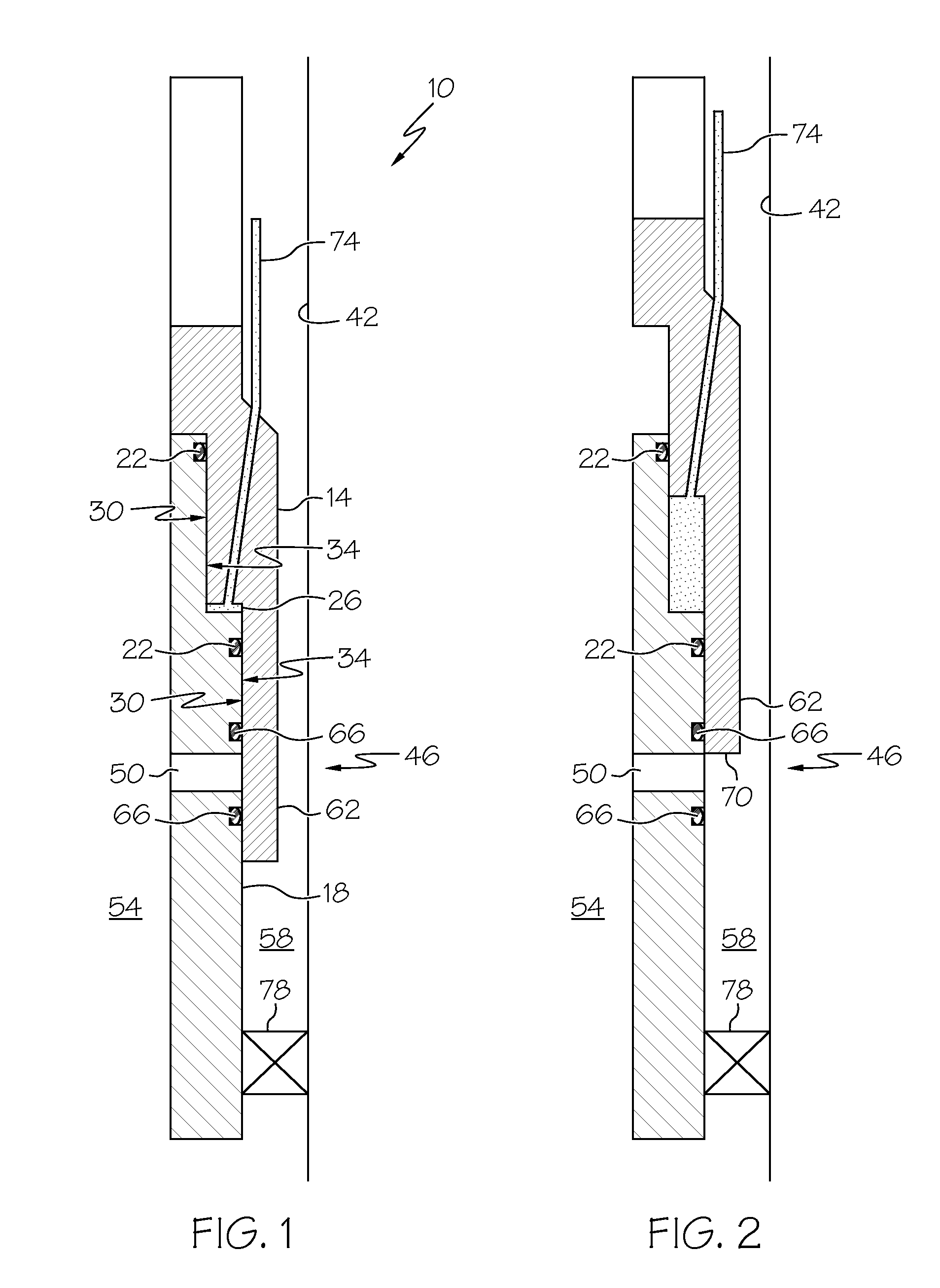
[0008]A detailed description of one or more embodiments of the disclosed apparatus and method are presented herein by way of exemplification and not limitation with reference to the Figures.

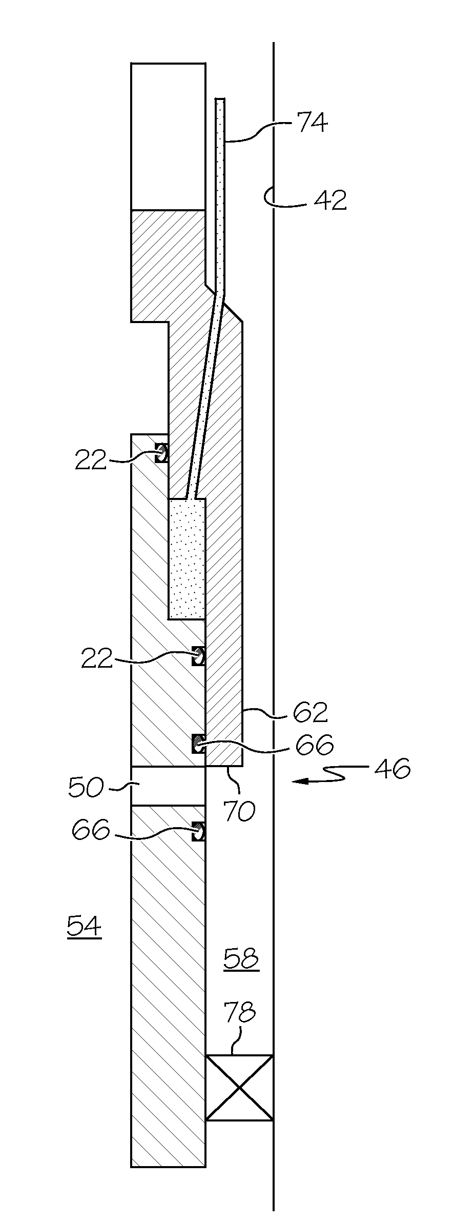
[0009]Referring to FIGS. 1 and 2, an embodiment of an energy storage device disclosed herein is illustrated at 10. The energy storage device 10 includes, a first member 14, shown herein is a first tubular, a second member 18, shown herein as a second tubular that is slidably engaged with the first tubular 14, two seals 22 and a cavity 26. The cavity 26 is defined by an annular space between the two seals 22 and inner surface 30 of the first tubular 14 and outer surface 34 of the second tubular 18. The seals 22 slidably sealingly engage with the inner surfaces 30 thereby allowing the first tubular 14 to move longitudinally relative to the second tubular 18 altering a volume of the cavity 26 in the process. In this embodiment the first tubular 14 is positioned above the second tubular 18 such that ...


PUM


Abstract

An energy storage device a first member and a second member that is slidably engaged with the first member. There are at least two seals that slidably seal the first member to the second member and define a cavity therebetween that varies in volume with relative movement between the first member and the second member. The first member is biased toward the second member in a direction that resisted increases in volume of the cavity.

Description

BACKGROUND[0001]Energy storage devices that rely on a pressurized gas in a chamber are well known and work well for their intended purpose. Over an extended period of time, however, leakage of the gas filled chamber can cause the energy stored to dissipate even to the point of having inadequate energy to actuate an actuator in operable communication with the energy storage device. Devices and methods, therefore, to overcome the aforementioned drawback would be well received in industry.BRIEF DESCRIPTION[0002]Disclosed herein is an energy storage device. The storage device includes a first member and a second member that is slidably engaged with the first member. There are at least two seals that slidably seal the first member to the second member and define a cavity therebetween that varies in volume with relative movement between the first member and the second member. The first member is biased toward the second member in a direction that resisted increases in volume of the cavity...

Claims


Application Information

Patent Timeline
Patent Type & Authority Applications(United States)
IPC IPC(8): F15B1/027
CPCE21B34/10E21B41/00F15B1/04Y02E60/15F15B2201/215F15B2201/312F15B2201/21Y02E60/16
Inventor FARMER, JACK DAVID
Owner BAKER HUGHES INC
Why Eureka
Try Eureka