Vibration Motor Surface Mounting Structure and Vibration Motor

Inactive Publication Date: 2011-10-06
MINEBEA MOTOR MFG
View PDF4 Cites 7 Cited by
  • Summary
  • Abstract
  • Description
  • Claims
  • Application Information

AI Technical Summary

Benefits of technology

[0022]According to the present invention, it is possible to provide a vibration motor surface mounting structure that can

Problems solved by technology

However, in the conventional structure disclosed in Unexamined Japanese Patent Application KOKAI Publication No. 2009-77521, it is necessary to prepare a metal holder separately from the vibration motor and in addition a process of assembling the metal holder on the motor body is necessary, creating the problem that production costs increase.
In addition, pro

Method used


Image

  • Vibration Motor Surface Mounting Structure and Vibration Motor
  • Vibration Motor Surface Mounting Structure and Vibration Motor
  • Vibration Motor Surface Mounting Structure and Vibration Motor

Examples


Embodiment Construction

[0037]The vibration motor surface mounting structure according to the preferred embodiments of the present invention will now be described in detail below with reference to the accompanying drawings.

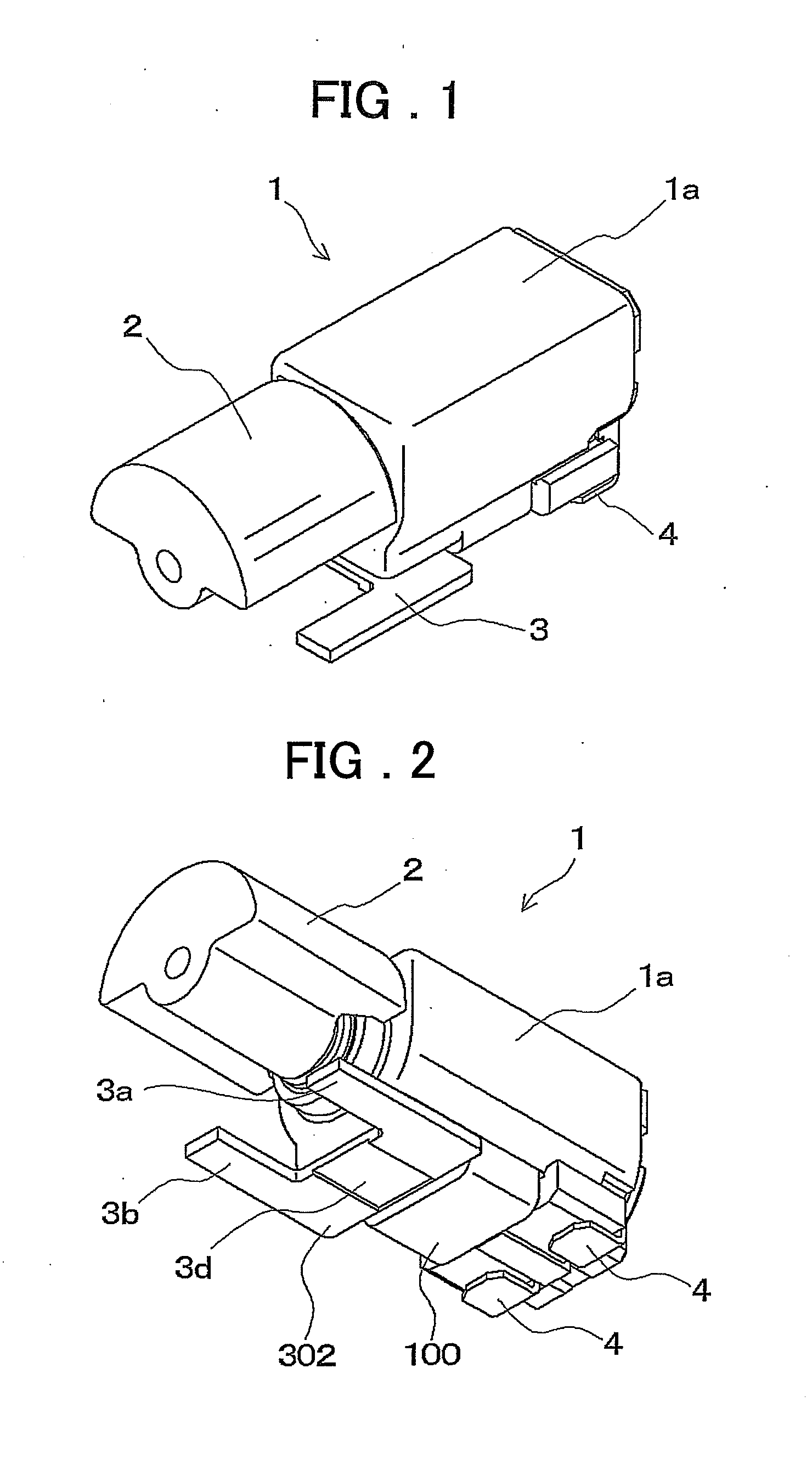
[0038]FIG. 1 is a perspective view of a vibration motor according to a first embodiment of the present invention, as viewed from above.

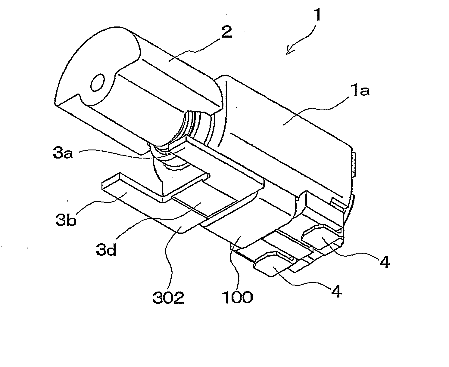
[0039]In addition, FIG. 2 is a perspective view of the vibration motor of FIG. 1 as viewed from below.

[0040]An eccentric weight 2 is mounted on a rotating shaft of a motor 1. When the rotating shaft of this motor 1 rotates, the eccentric weight 2 is also rotated, thereby generating vibrations. The motor 1 according to the present embodiment has a diameter of for example just less than 4 mm.

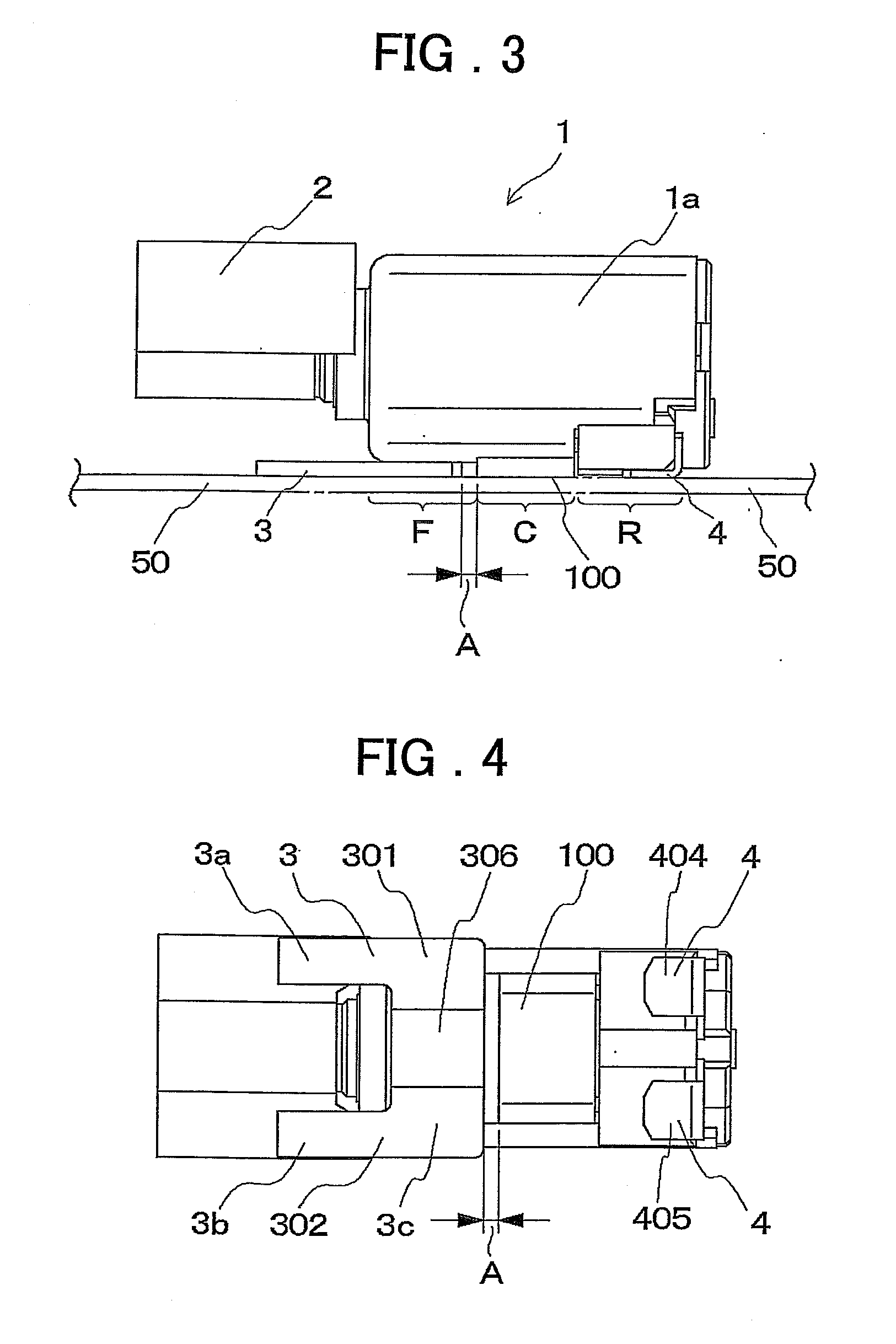
[0041]A support member 3 for supporting the motor 1 on a printed circuit board is provided on the bottom surface of the motor 1, and in addition, terminals 4 for supplying electric to drive the rotating shaft of the motor 1 to rotate are exposed.

[0042]FIG. 3 is a side v...


PUM


Abstract

In order to provide a vibration motor surface mounting structure capable of preventing a vibration motor from tipping over without using a part such as metal holder requiring complicated assembly, for a vibration motor having an eccentric weight mounted on the rotating shaft of the motor and mounted on a surface of a printed circuit board, a support member having extensions extending to the side of the rotating shaft on which the eccentric weight is mounted is used, a portion of this is fixed to the motor or the frame thereof, and a bottom surface including the extensions of the support member is secured to the mounting surface of the printed circuit board by soldering.

Description

BACKGROUND OF THE INVENTION[0001]1. Field of the Invention[0002]The present invention relates to a vibration motor surface mounting structure used for body sensory vibration in game equipments or portable communication equipments such as mobile phones or PHS, and a vibration motor equipped with this surfaces mounting structure.[0003]In mobile communication equipments, in addition to a method of sounding a ring tone to alert a cell phone holder of an incoming call, there is also a method of alerting the cell phone holder of an incoming call by causing him to feel vibrations caused by rotation of an eccentric weight of a built-in vibration motor provided internally, and these modes can be switched as necessary. In addition, there are game systems in which enjoyment is enhanced by conveying to the user a vibration generated by a vibration motor inside the equipment in conjunction with the progress of a game.[0004]This type of vibration motor is fixed inside the equipment and conveys ge...

Claims


Application Information

Patent Timeline
IPC IPC(8): H02K7/075F16M13/02F16B47/00
CPCB06B1/16F16M7/00H02K2211/03H02K5/00H02K7/061F16M9/00
Inventor KADOWAKI, DAICHISATO, KAZUAKI
Owner MINEBEA MOTOR MFG
Why Eureka
Try Eureka