Split magnetic resonance imaging system

a magnetic resonance imaging and split technology, applied in the field of magnetic resonance imaging (mri) systems, can solve problems such as difficult movement and installation

Inactive Publication Date: 2011-10-06
VIEWRAY TECH
View PDF4 Cites 40 Cited by
  • Summary
  • Abstract
  • Description
  • Claims
  • Application Information

AI Technical Summary

Benefits of technology

[0015]The first and second MRI magnet housings can be substantially cylindrical, allowing for accommodating a patient bed wi

Problems solved by technology

However, such systems typically include large components, making them difficult to move and install, especially i

Method used


Image

  • Split magnetic resonance imaging system
  • Split magnetic resonance imaging system
  • Split magnetic resonance imaging system

Examples


Embodiment Construction

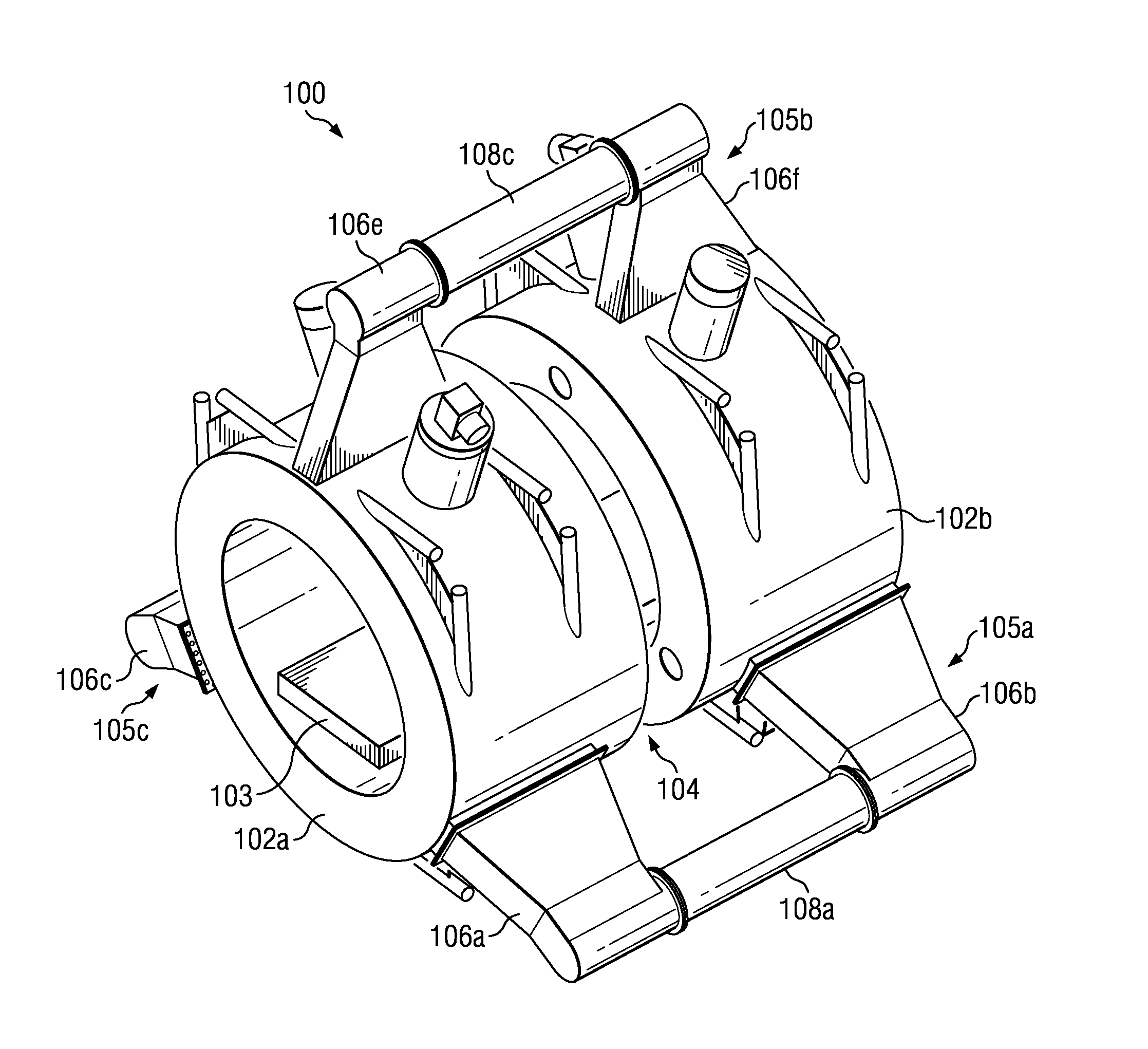
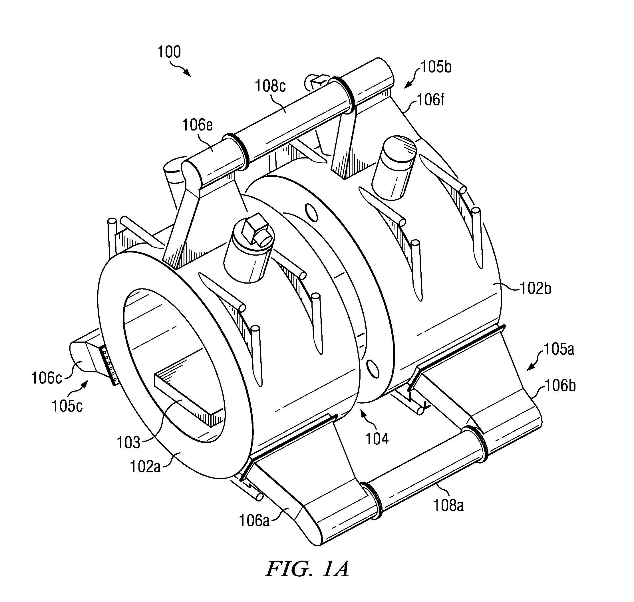
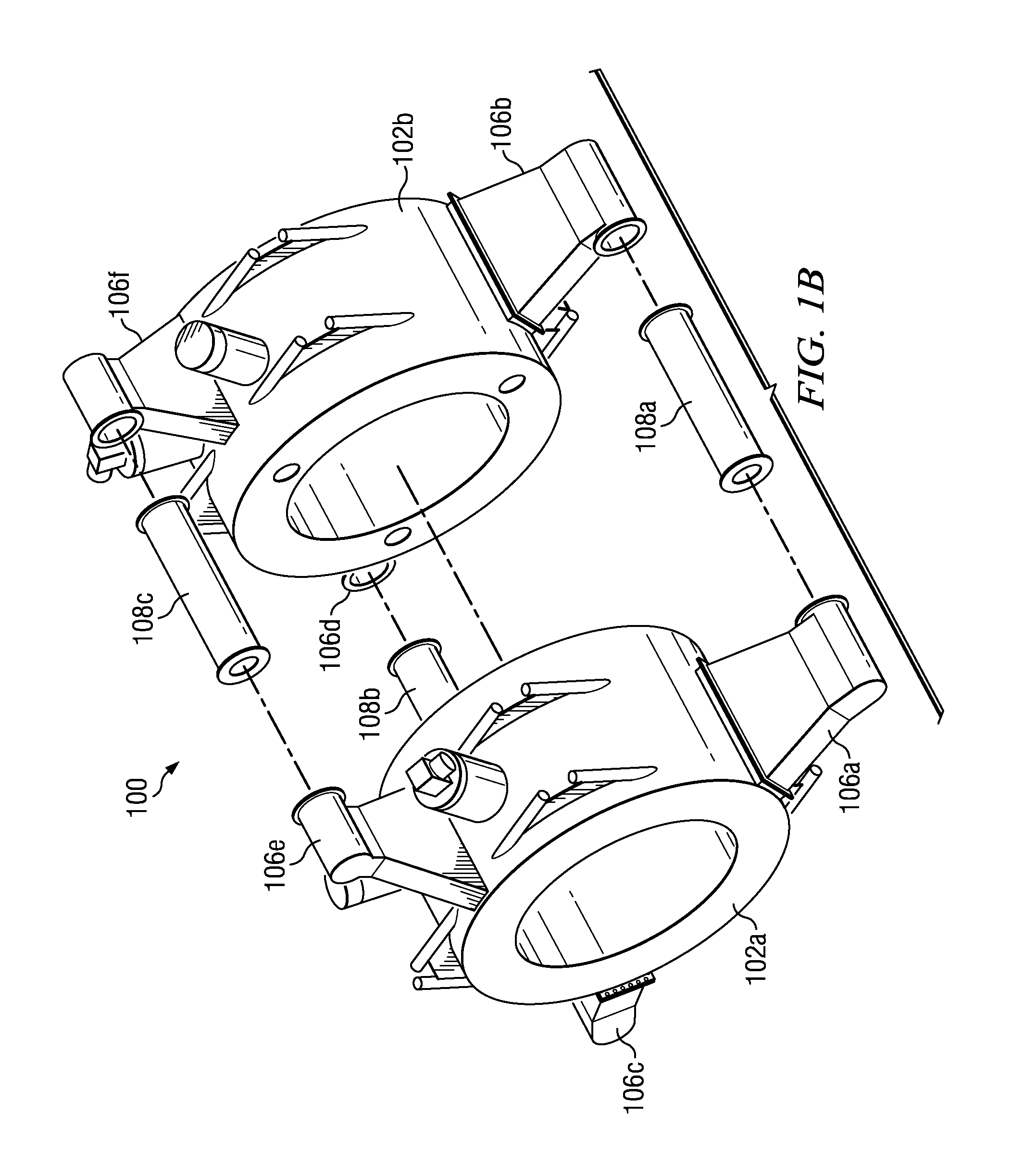
[0020]FIGS. 1A through 1C show perspective views of a split-magnet MRI system 100. FIGS. 1A shows a fully assembled view of the MRI system 100, FIG. 1B shows a partially exploded view of the MRI system 100, and FIG. 1C shows a further exploded view of the MRI system 100.

[0021]The MRI system 100 has a split MRI configuration that can more easily be relocated and installed compared to prior MRI systems. The disclosed MRI system 100 is preferrably constructed so that it can be disassembled, moved, and then installed into existing facilities and shielded vaults. The MRI system 100 includes first and second cylindrical main MRI magnet housings 102a and 102b for housing respective cylindrical superconducting MRI main magnets 101a and 101b, respectively (shown in FIG. 3). The MRI main magnets 101a and 101b can be operated to produce a uniform magnetic field in a Field-of-View (FOV) for imaging that is generally centered in a gap 104 between the two magnet housings 102a and 102b for imaging...


PUM


Abstract

A magnetic resonance imaging (MRI) system includes a split magnet system having a pair of MRI magnet housings separated by gap. A pair of main MRI magnets are disposed within respective MRI magnet housings. A plurality of buttress assemblies are attached to the MRI magnet housings. Some or all of the buttress assemblies are provided with removable connections to the MRI magnet housings. This allows for partial disassembly of the MRI system for improved transport and maneuverability for relocating the MRI system. The MRI system can include a gantry in the gap for supporting a radiation therapy system. Also, the removably buttress assemblies can be used for housing conduits, such as electrical and fluid conduits, between the pair of MRI magnet housings.

Description

RELATED APPLICATION[0001]This application claims the benefit of U.S. Provisional Application No. 61 / 307,665, filed Feb. 24, 2010, titled “Split MRI System,” which is hereby incorporated by reference.BACKGROUND[0002]1. Technical Field[0003]The present application relates to magnetic resonance imaging (MRI) systems, particularly MRI systems that include a split main magnet.[0004]2. Related Art[0005]Magnetic Resonance Imaging (MRI), or nuclear magnetic resonance imaging (NMRI), is primarily a medical imaging technique most commonly used in radiology to visualize the internal structure and function of the body. MRI is described, for example, by E. MARK HAACKE ET AL., MAGNETIC RESONANCE IMAGING: PHYSICAL PRINCIPLES AND SEQUENCE DESIGN (Wiley-Liss 1999), which is hereby incorporated herein by reference.[0006]A variety of MRI systems are known and are in wide use today. However, such systems typically include large components, making them difficult to move and install, especially in an exi...

Claims


Application Information

Patent Timeline
IPC IPC(8): G01R33/44
CPCA61B5/055G01R33/3806A61N2005/1055G01R33/3802G01R33/3856G01R33/4808A61N5/1049
Inventor DEMPSEY, JAMES F.PATRICK, JOHN L.SHVARTSMAN, SHMARYU M.DEMEESTER, GORDON D.
Owner VIEWRAY TECH
Why Eureka
Try Eureka