Locking screw driver with increased torsional strength

a technology of locking screw and torsional strength, which is applied in the field of orthopedic tools, can solve the problems of further limiting the strength of components and limited torsional strength of components, and achieve the effect of improving torsional strength

Inactive Publication Date: 2011-10-06
ZIMMER INC
View PDF5 Cites 12 Cited by
  • Summary
  • Abstract
  • Description
  • Claims
  • Application Information

AI Technical Summary

Benefits of technology

[0008]The present invention provides an orthopedic tool for implanting a bone screw and a method of manufacturing the same. The orthopedic tool includes a head that is shaped to lock onto the bone screw and that has improved torsional strength.

Problems solved by technology

As a result, the components may have limited torsional strength.
Hollowing out the bone screws and their corresponding drivers to create cannulated components that accommodate a guide wire may further limit the strength of the components.

Method used


Image

  • Locking screw driver with increased torsional strength
  • Locking screw driver with increased torsional strength
  • Locking screw driver with increased torsional strength

Examples


Embodiment Construction

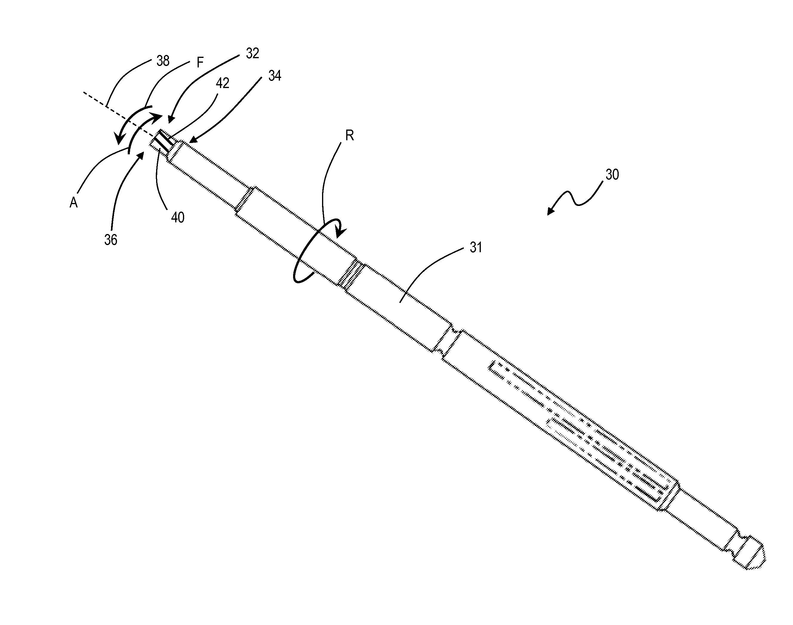
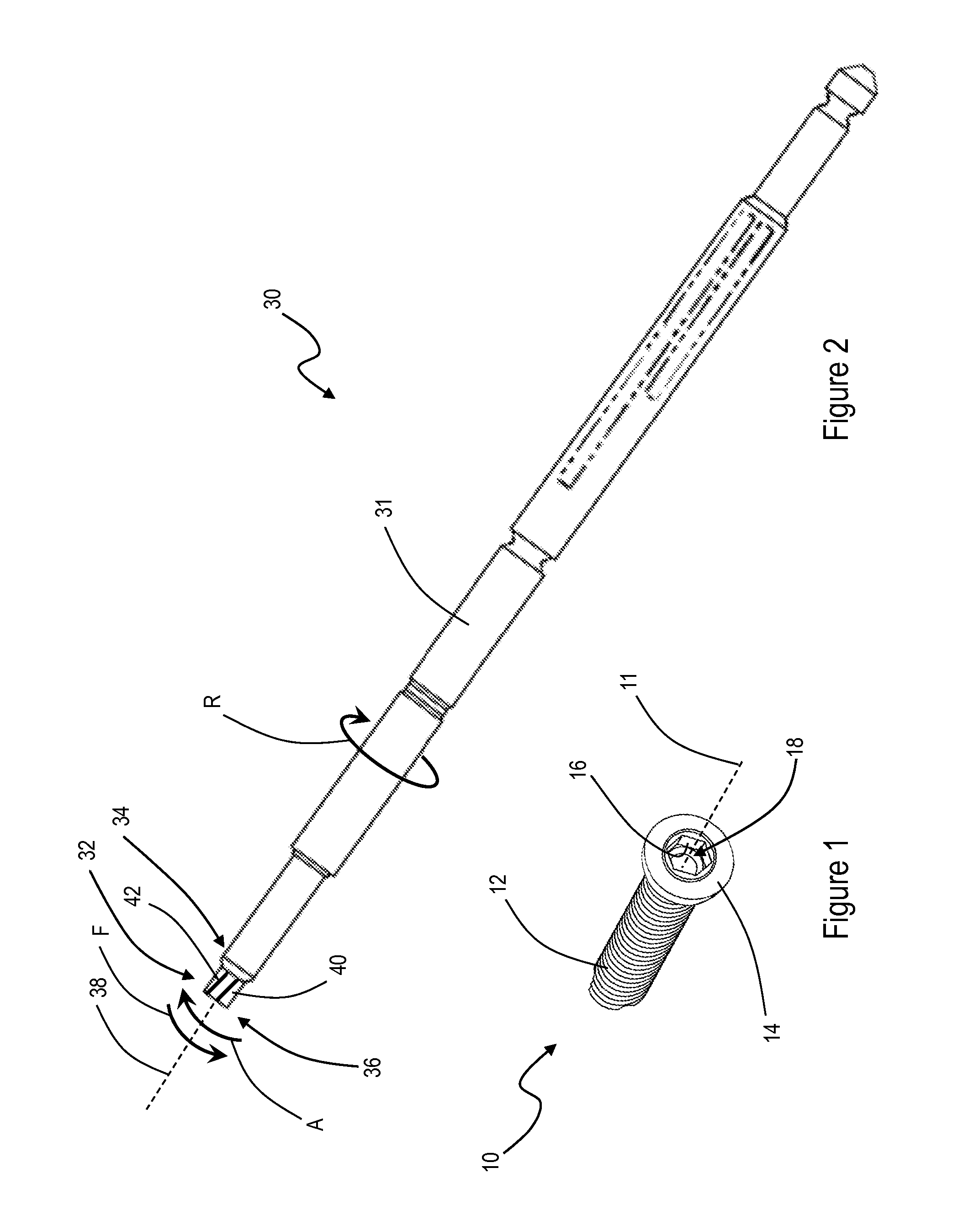
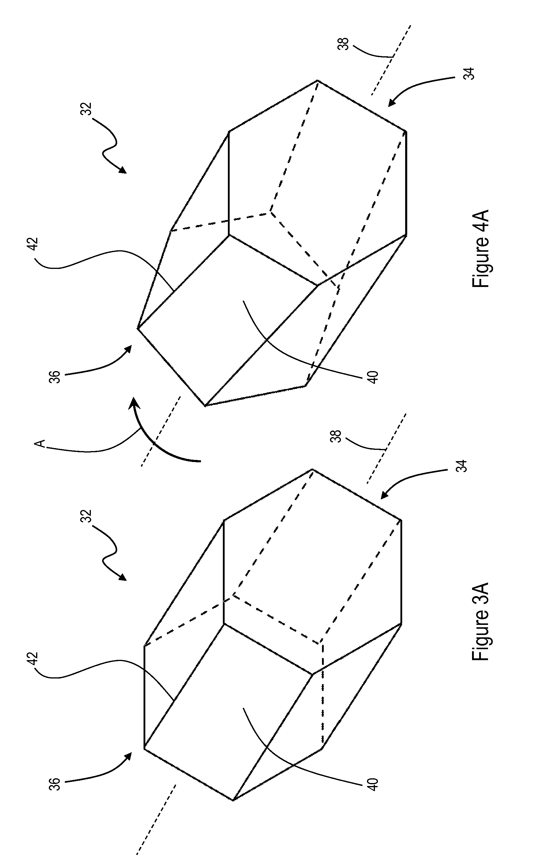
[0022]FIG. 1 depicts an exemplary bone screw 10. Bone screw 10 extends along longitudinal axis 11 and includes threaded shaft 12 and head 14. Head 14 of bone screw 10 includes walls 16 that define internal socket 18 having a non-circular cross section. According to an exemplary embodiment of the present invention, socket 18 is polygonal in shape. For example, walls 16 may define socket 18 that is hexagonal in shape, as shown in FIG. 1, triangular in shape, rectangular in shape, or octagonal in shape.

[0023]To facilitate alignment and insertion of bone screw 10 into a patient's bone, bone screw 10 may be cannulated. As shown in FIG. 1, bone screw 10 includes longitudinal bore 20 that extends entirely through threaded shaft 12 and head 14 of bone screw 10 along longitudinal axis 11. In use, a surgeon may pass a guide wire (not shown) through longitudinal bore 20 of bone screw 10 to guide positioning of bone screw 10.

[0024]Bone screw 10 is configured to mate with a corresponding orthope...


PUM

PropertyMeasurementUnit
angleaaaaaaaaaa
angleaaaaaaaaaa
angleaaaaaaaaaa

Abstract

An orthopedic tool for implanting a bone screw and a method of manufacturing the same. The orthopedic tool includes a head that is shaped to lock onto the bone screw and that has improved torsional strength.

Description

BACKGROUND[0001]1. Field of the Invention[0002]The present invention relates to an orthopedic tool. More particularly, the present invention relates to an orthopedic tool for implanting bone screws, and to a method of manufacturing the same.[0003]2. Description of the Related Art[0004]Orthopedic components, such as prosthetic joints and bone plates, may be secured to a patient's bone using bone screws. For example, a surgeon may position a bone plate to extend across a fracture line, and then the surgeon may secure the bone plate in place by inserting a plurality of bone screws through apertures in the bone plate and into the patient's bone.[0005]To facilitate proper alignment of the bone screw within each aperture of the bone plate and to ease the insertion thereof, the surgeon may utilize a guide wire and a cannulated bone screw. First, the surgeon may insert the guide wire into the patient's bone at the point where the surgeon intends for the bone screw to be positioned. Then, th...

Claims


Application Information

Patent Timeline
Patent Type & Authority Applications(United States)
IPC IPC(8): A61B17/56B23P11/00
CPCA61B17/8875A61B17/888Y10T29/49826B23P15/00A61B17/8888
Inventor LOWER, JERRY L.
Owner ZIMMER INC
Why Eureka
Try Eureka