Method and Arrangement for Spatial Display

a spatial display and spatial technology, applied in optics, instruments, electrical equipment, etc., can solve the problems of high light loss, difficult production of lenticular lenses, and failure to gain the widespread use of autostereoscopic systems, so as to improve perceptibility, improve brightness, and improve perceptibility

Inactive Publication Date: 2011-10-13
VISUMOTION
View PDF5 Cites 11 Cited by
  • Summary
  • Abstract
  • Description
  • Claims
  • Application Information

AI Technical Summary

Benefits of technology

[0012]The present invention is based on the problem of creating a way of autostereoscopic display on the basis of the barrier technology, in order improve perceptibility for

Problems solved by technology

Attempts to gain autostereoscopic systems widespread use were unsuccessful for a long time, though.
Here just as with all barrier methods, the disadvantage is the high light loss.
However, lenticular lenses are complicated to produce, and the process of manufacturing a 3D display ba

Method used


Image

  • Method and Arrangement for Spatial Display
  • Method and Arrangement for Spatial Display
  • Method and Arrangement for Spatial Display

Examples


Embodiment Construction

[0190]None of the drawing is made to scale. This also, and in particular, applies to angular dimensions.

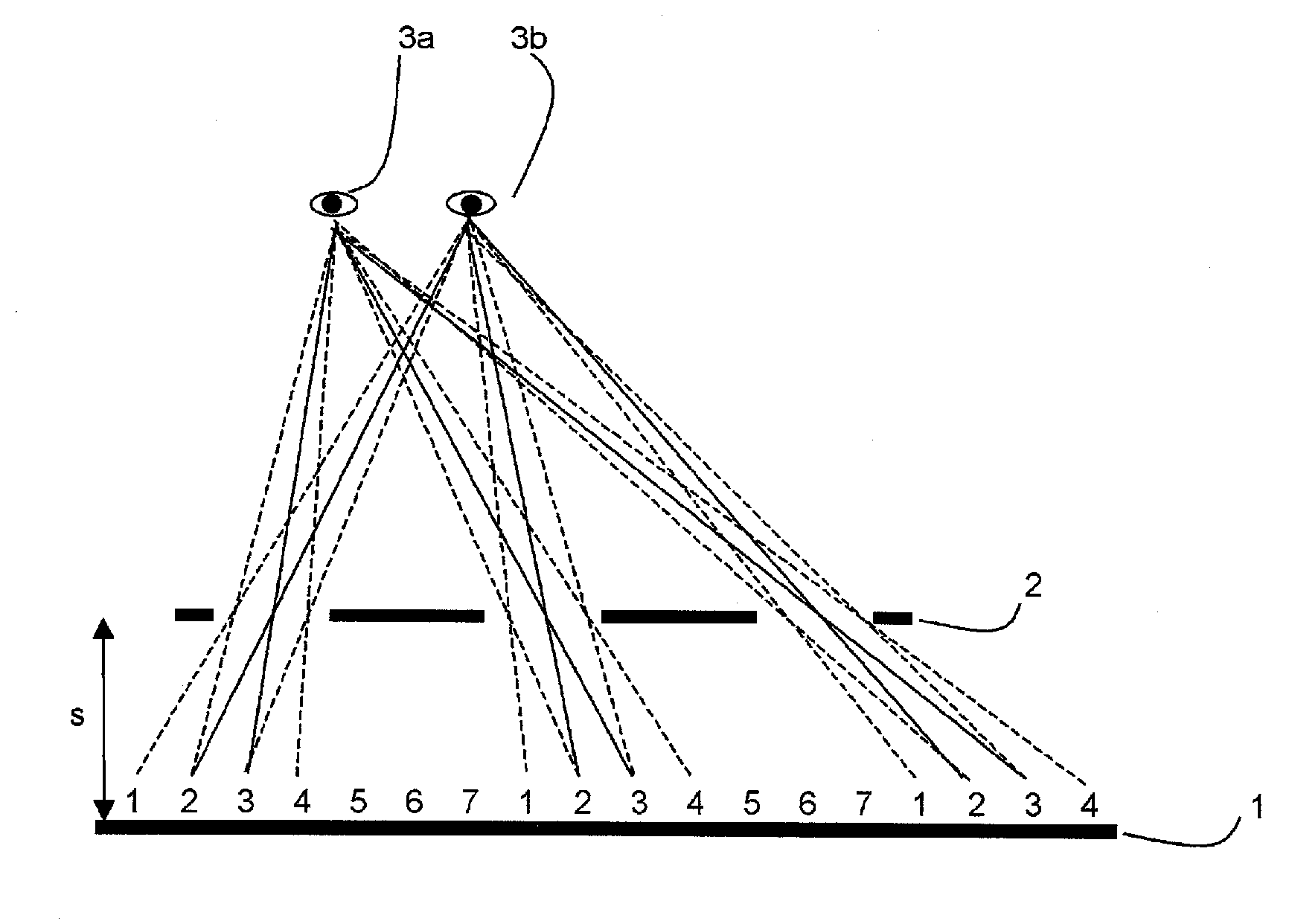
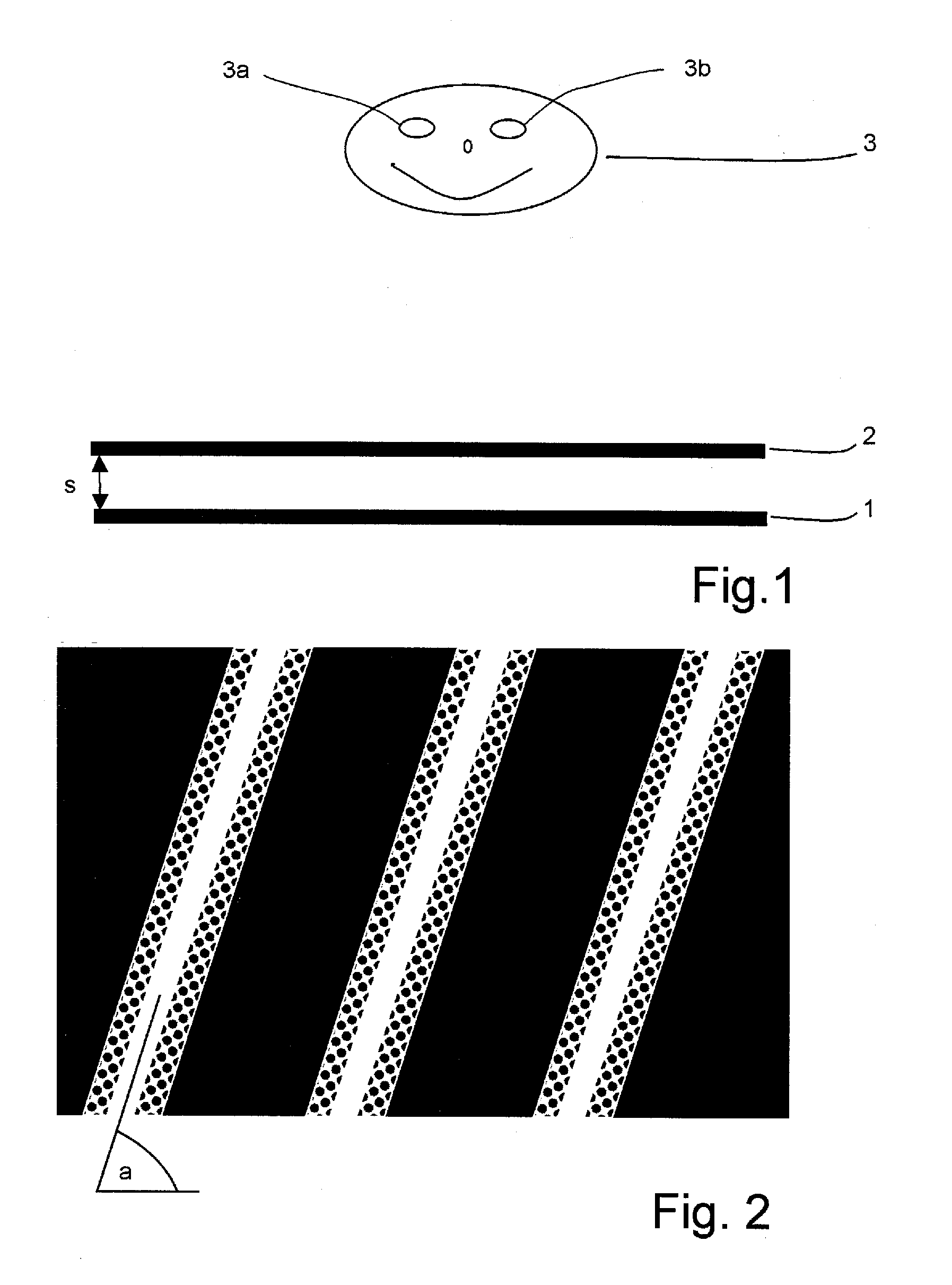
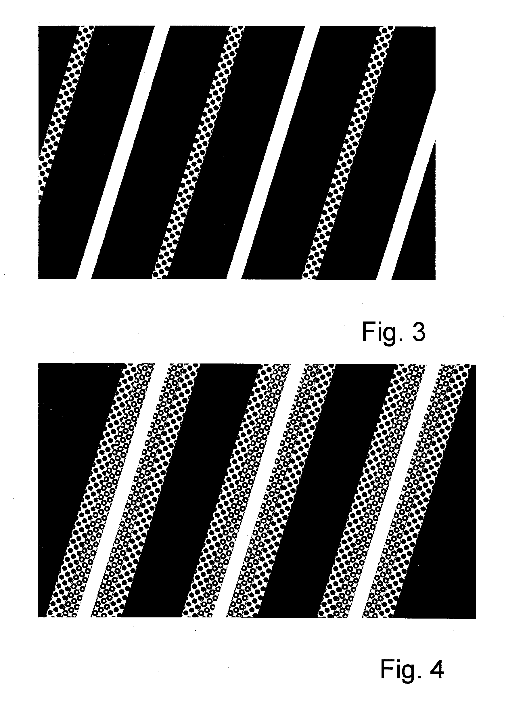
[0191]FIG. 1 shows the schematic setup for implementing the invented method for spatial display. On the grid 1 of pixels x(i,j) with rows i and columns j, bits of partial information from different views A(k) with k=1, . . . , n and n>1 are made visible. Arranged in front of the grid 1 of pixels x(i,j) at a distance s is a parallax barrier screen 2, which contains opaque, semitransparent and transparent segments, with the transparent and the semitransparent segments essentially corresponding to stripes that are delimited by straight-line edges, which run uninterruptedly from one margin of the parallax barrier screen 2 to an opposite margin. An example of such a parallax barrier screen 2 is shown as a sectional view in FIG. 2.

[0192]Because of the viewing restriction effected by the at least one parallax barrier screen 2, the two eyes 3a, 3b of one or several viewers 3 will see at l...


PUM


Abstract

The invention relates to a method and an arrangement for spatial display, in particular to a display that can be perceived in three dimensions simultaneously by several viewers without viewing aids, also known as autostereoscopic visualization. With the invented method, bits of partial information from different views A(k) with k=1, . . . , n and n>1 are made visible on a grid (1) of pixels x(i,j) with rows (i) and columns (j), and at least one parallax barrier screen (2) is arranged in front of or behind the grid (1) of pixels x(i,j) at a distance s, which contains at least semitransparent segments, the segments corresponding essentially to stripes delimited by straight-line edges, which run uninterruptedly from one margin of the parallax barrier screen (2) to an opposite or adjoining margin, so that one or several viewers (3), because of the viewing restriction effected by the at least one parallax barrier screen (2), will see at least partially different pixels x(i,j) and/or parts thereof with each of their two eyes (3a, 3b), so that each of the two eyes (3a, 3b) perceives at least partially different views A(k) and, thus, a spatial visual impression results.

Description

RELATED APPLICATIONS[0001]This Application is a Continuation application of International Application PCT / DE2009 / 050010, filed on Feb. 26, 2009, which in turn claims priority to German Patent Application No. DE 10 2008 062 790.9, filed Dec. 19, 2008, both of which are incorporated herein by reference in their entirety.FIELD OF THE INVENTION[0002]The invention relates to the field of spatial display, in particular to a display that can be perceived in three dimensions simultaneously by several viewers without viewing aids, also known as autostereoscopic visualization.BACKGROUND OF THE INVENTION[0003]Approaches to the said field have been existing for quite some time. Frederic Ives, a pioneer in this field, presented a system with a “line screen” for 3D display in GB 190418672 A. The article “Theory of parallax barriers” by Sam H. Kaplan, Journal of SMPTE Vol. 59, No 7, pp 11-21, July 1952, describes fundamental findings about the use of barrier screens for 3D display.[0004]Attempts t...

Claims


Application Information

Patent Timeline
IPC IPC(8): G02B27/22G02B30/32
CPCG02B27/2214H04N13/0415H04N13/0409H04N13/31H04N13/317G02B30/32G02B30/27
Inventor KLIPPSTEIN, MARKUSOTTE, STEPHAN
Owner VISUMOTION
Why Eureka
Try Eureka