Anti-dysphotopic intraocular lens and method

a technology of intraocular lens and anti-dysphotopsia, applied in the field of intraocular lens implants and surgical methods, can solve the problems of negative dysphotopsia and posterior iris chafing, and achieve the effect of reducing the occurrence of nd

Active Publication Date: 2011-10-13
MASKET SAMUEL
View PDF2 Cites 53 Cited by
  • Summary
  • Abstract
  • Description
  • Claims
  • Application Information

AI Technical Summary

Problems solved by technology

If left untreated, cataracts may result in blindness.
However, capsular bag fixation may result in negative dysphotopsia (“ND”), which is a visual phenomenon that occurs after an uncomplicated cataract surgery.
This approach, while improving the symptoms of ND, may again lead to posterior iris chafing.

Method used


Image

  • Anti-dysphotopic intraocular lens and method
  • Anti-dysphotopic intraocular lens and method
  • Anti-dysphotopic intraocular lens and method

Examples


Embodiment Construction

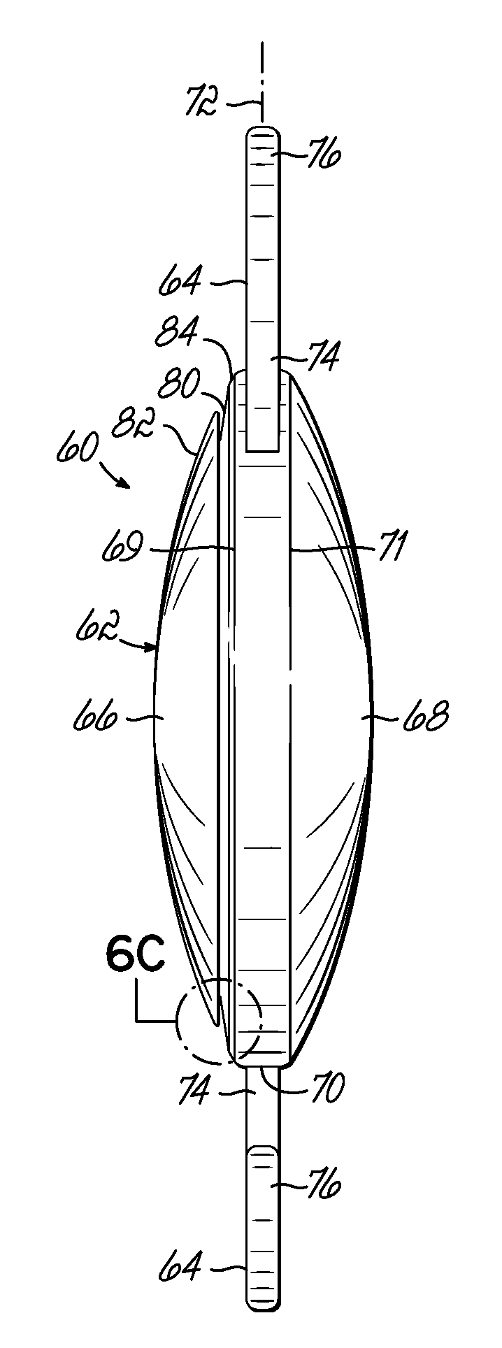
[0034]Turning now to the figures, and to FIGS. 6A and 6B in particular, one embodiment of an IOL 60 in accordance with the present invention is shown. While the IOL 60 of FIGS. 6A and 6B is shown as a biconvex lens 62 having at least two diametrically opposed haptic members 64, other lens designs may also be used, including, for example, a convex-concave IOL 60a (FIG. 7A), a convex-planar IOL 60b (FIG. 7B), or other designs as desired. The biconvex lens 62 comprises a transparent structure constructed from a polymeric, silicone, acrylic, or other suitable moldable material having a refractive index similar to the native lens 24 (FIG. 1). Anterior and posterior portions 66, 68 of the biconvex lens 62 converge at a lateral, circumferential edge 70 of the IOL 60. As shown, the circumferential edge 70 may be a wall having a length of about 1 mm with an anterior edge 69 and a posterior edge 71. However, in some embodiments, the anterior and posterior portions 66, 68 may converge at a com...


PUM


Abstract

An intraocular lens implant includes a lens having an anterior portion, a posterior portion, and a circumferential edge located therebetween. An annular notch is formed in the anterior portion and oriented in an anteriorly-directed orientation.

Description

[0001]The present application claims the filing benefit of co-pending U.S. Provisional Patent Application No. 61 / 323,060, filed on Apr. 12, 2010, the disclosure of which is incorporated herein by reference in its entirety.FIELD OF THE INVENTION[0002]This present invention relates generally to intraocular lens implants and, more particularly, to intraocular lens implants and surgical methods for reducing negative dysphotopsia.BACKGROUND OF THE INVENTION[0003]The human eye is the sensory organ for reacting to light. As shown in FIG. 1, the anatomical structure of an anterior segment of the eye 10 is shown and includes a transparent outer layer, the cornea 12, that is continuous with an opaque sclera 14 forming the lateral white portion of the eye 10. The cornea 12 encloses an anterior chamber 16 and posterior chamber 18, both filled with aqueous humor. The anterior and posterior chambers 16, 18 are separated by the iris 20, which is a circular, muscular structure that controls the dia...

Claims


Application Information

Patent Timeline
Patent Type & Authority Applications(United States)
IPC IPC(8): A61F2/16
CPCA61F2/1613A61F2/1648A61F2002/1697A61F2002/1699A61F2220/0008A61F2/1694
Inventor MASKET, SAMUEL
Owner MASKET SAMUEL
Why Eureka
Try Eureka