Clamp Member, Clamp and Anastomotic Apparatus
a technology of anastomosis apparatus and clamp, which is applied in the direction of surgical staples, paper/cardboard containers, surgical forceps, etc., can solve the problems of complicated execution sequences and injury to biological tissues, and achieve efficient and stable anastomosis of organ tissue, stable holding, and easy and efficient gripping
- Summary
- Abstract
- Description
- Claims
- Application Information
AI Technical Summary
Benefits of technology
Problems solved by technology
Method used
Image
Examples
first embodiment
[0187]the present invention will now be explained with reference to the accompanying figures.
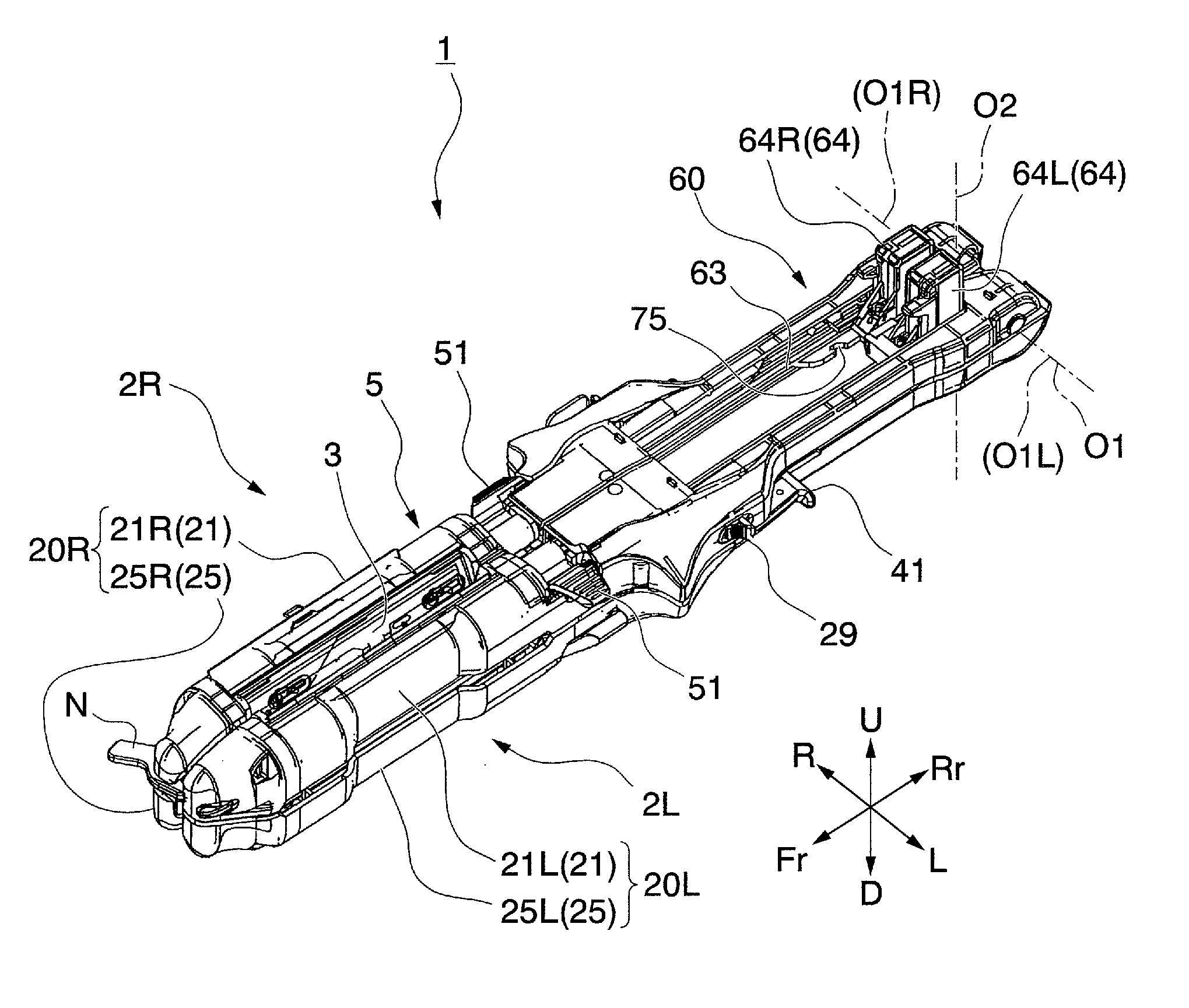
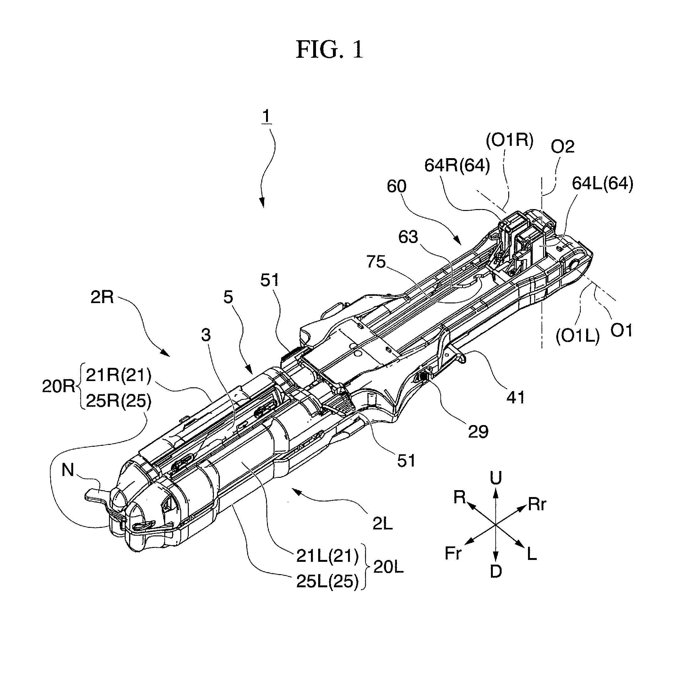
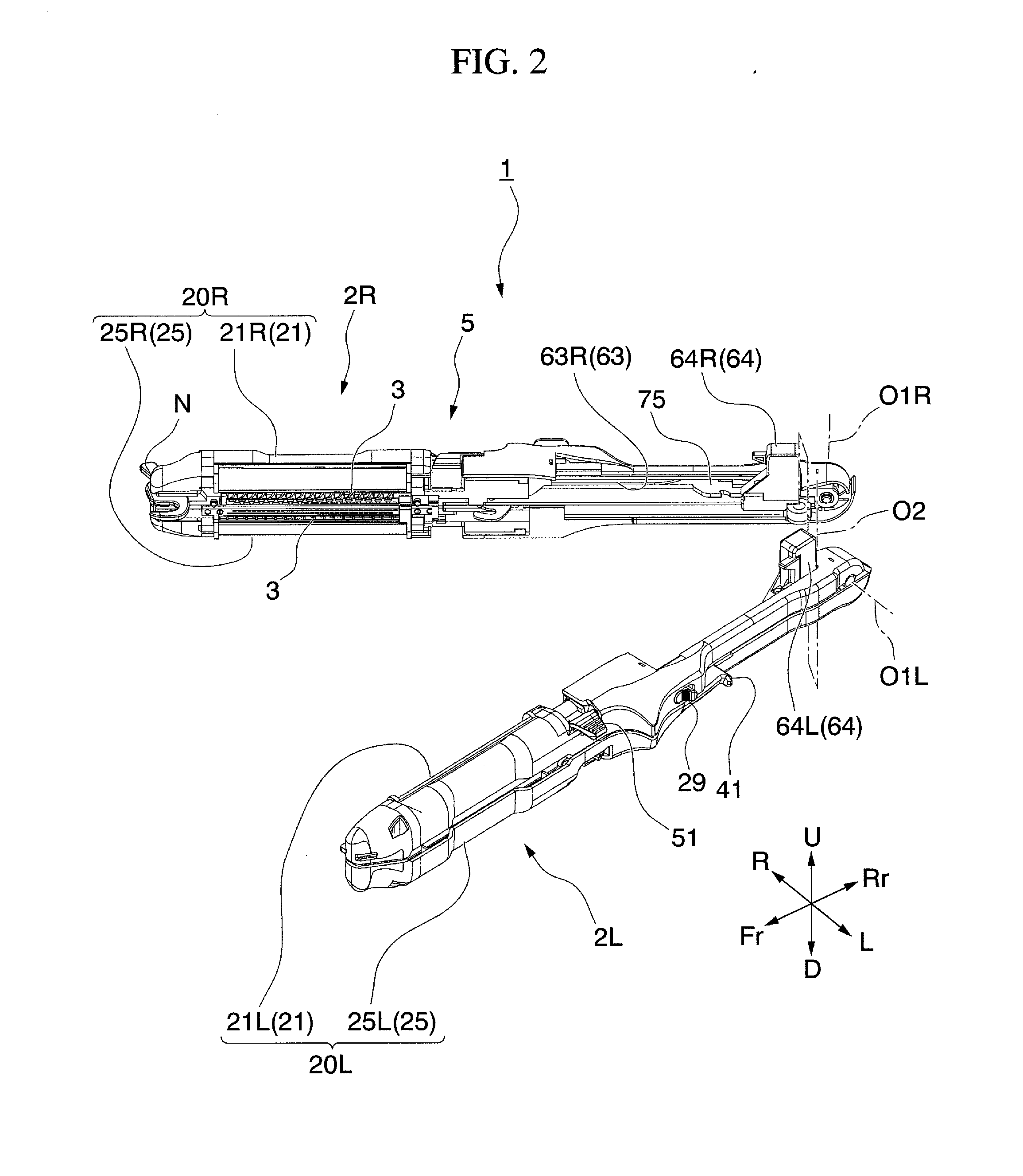
[0188]FIGS. 1 through 3 are views showing the anastomotic apparatus according to the present invention. The numeric symbol 1 indicates the anastomotic apparatus while numeric symbols 2R and 2L indicate the clamps.
[0189]FIGS. 4 and 5 show paired clamp members 20R (composed of clamp member 21R and clamp member 25R) which form clamp 2R, and paired clamp members 20L (composed of clamp member 21L and clamp member 25L) which form clamp 2L. FIG. 6 shows clamp member 25L.
[0190]The numeric symbols R, L, Fr, Rr, U and D on the coordinate axes shown in FIGS. 1 through 6 indicate direction associated with the anastomotic apparatus 1 and its composing members, with right (R), left (L), Fr (distal end side), up (U) and down (D) indicated for the case when the rear side Rr (referred to as the “handheld side” hereinafter) of the anastomotic apparatus 1 is held in the hand.
[0191]As shown in FIGS. 1 through 3...
second embodiment
[0353]Next, the present invention will be explained with reference to the figures.
[0354]FIGS. 37 and 38 are views showing the anastomotic apparatus according to the present invention. Numeric symbol 101 indicates the anastomotic apparatus and numeric symbols 102R,102L indicate the clamps.
[0355]FIGS. 39 and 40 are views showing the paired clamp member 120R (formed from clamp member 121R and clamp member 125R) which composes the clamp 102R, and paired clamp member 120L (formed from clamp members 121L and clamp members 125L) which composes the clamp 102L. FIG. 41 is a view showing the clamp member 125L.
[0356]The symbols R, L, Fr, Rr, U and D along the coordinate axes shown in FIGS. 37 through 41 show directions associated with anastomotic apparatus 1 and its composing members, and shows right (R), left (L), Fr(front), up (U) and down (D) when the rear Rr (“handheld side” hereinafter) of the anastomotic apparatus 1 is held on the handheld side.
[0357]As shown in FIGS. 37 and 38, the anas...
PUM
| Property | Measurement | Unit |
|---|---|---|
| angle | aaaaa | aaaaa |
| relative movement | aaaaa | aaaaa |
| surgical time | aaaaa | aaaaa |
Abstract
Description
Claims
Application Information
 - R&D
- Intellectual Property
- Life Sciences
- Materials
- Tech Scout
- Unparalleled Data Quality
- Higher Quality Content
- 60% Fewer Hallucinations
Browse by: Latest US Patents, China's latest patents, Technical Efficacy Thesaurus, Application Domain, Technology Topic, Popular Technical Reports.
© 2025 PatSnap. All rights reserved.Legal|Privacy policy|Modern Slavery Act Transparency Statement|Sitemap|About US| Contact US: help@patsnap.com


