Pressure activated lighted glove

Inactive Publication Date: 2011-10-27
THOMPSON JUSTIN +1
View PDF4 Cites 12 Cited by
  • Summary
  • Abstract
  • Description
  • Claims
  • Application Information

AI Technical Summary

Benefits of technology

[0003]In certain professions and hobbies, individuals must be prepared to handle poorly lit conditions on short notice. Thus, it has become customary for many individuals to carry flashlights on a day to day or at least on a regular basis. Though advances in technology have permitted flashlights to be minimized in size, it is still often inconvenient to juggle a traditional flashlight as well as other devices that may be required by the task at hand.
[0004]Take for example the profession of law enforcement. Officers of the law must often work in the dark under dangerous conditions: a combination that has made flashlights integral to officer safety. Unfortunately, using one hand for the purpose of carrying and operating a flashlight has often times interfered with other important law enforcement tasks such as firing a gun, calling for reinforcement using a radio or telephone, setting off tear gas, operating a bike or other vehicle, etc. A device such as a lighted glove, which could permit law enforcement officials to combat poorly lit conditions without interfering in the officers' other operations would intuitively be well received by this demographic.
[0005]Lighted gloves are not new to the art. Examples of typical lighted gloves may be found in U.S. Pat. No. 7,152,248, U.S. Pat. No. 6,592,235, U.S. Pat. No. 5,345,368, U.S. Pat. No. 5,283,722, U.S. Pat. No. 5,154,506, U.S. Pat. No. 5,124,892, U.S. Pat. No. 4,625,339, U.S. Pat. No. 5,535,105, U.S. Pat. No. 6,006,357, U.S. Pat. No. 6,892,397, U.S. Pat. No. 4,422,131, and U.S. Pat. No. D423758, all of which are hereby incorporated by reference. Among the problems with the lighted gloves existing in the art, and the most probable reason their use has not become wide spread among individuals such as police officers, is the fact that they can not be operated in a way that actually frees up hand space nor can their light sources be activated and deactivated quickly. In order to activate the light source on one of the existing lighted gloves, a user must use his non-gloved hand to find and

Problems solved by technology

Though advances in technology have permitted flashlights to be minimized in size, it is still often inconvenient to juggle a traditional flashlight as well as other devices that may be required by the task at hand.
Unfortunately, using one hand for the purpose of carrying and operating a flashlight has often times interfered with other important law enforcement tasks such as firing a gun, calling for reinforcement using a radio or telephone, setting off tear gas, operating a bike or other vehicle, etc.
Light

Method used


Image

  • Pressure activated lighted glove
  • Pressure activated lighted glove
  • Pressure activated lighted glove

Examples


Example

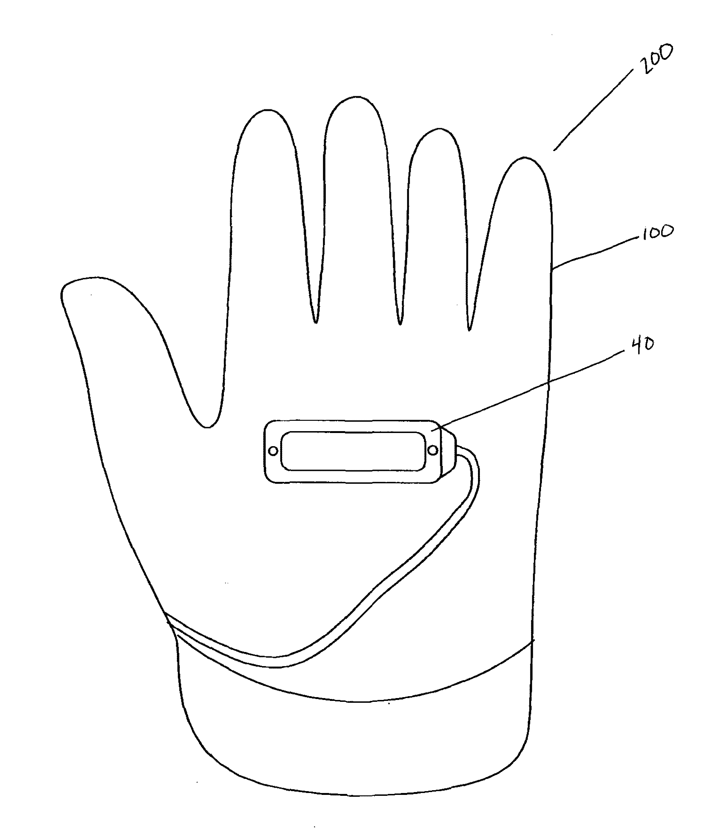
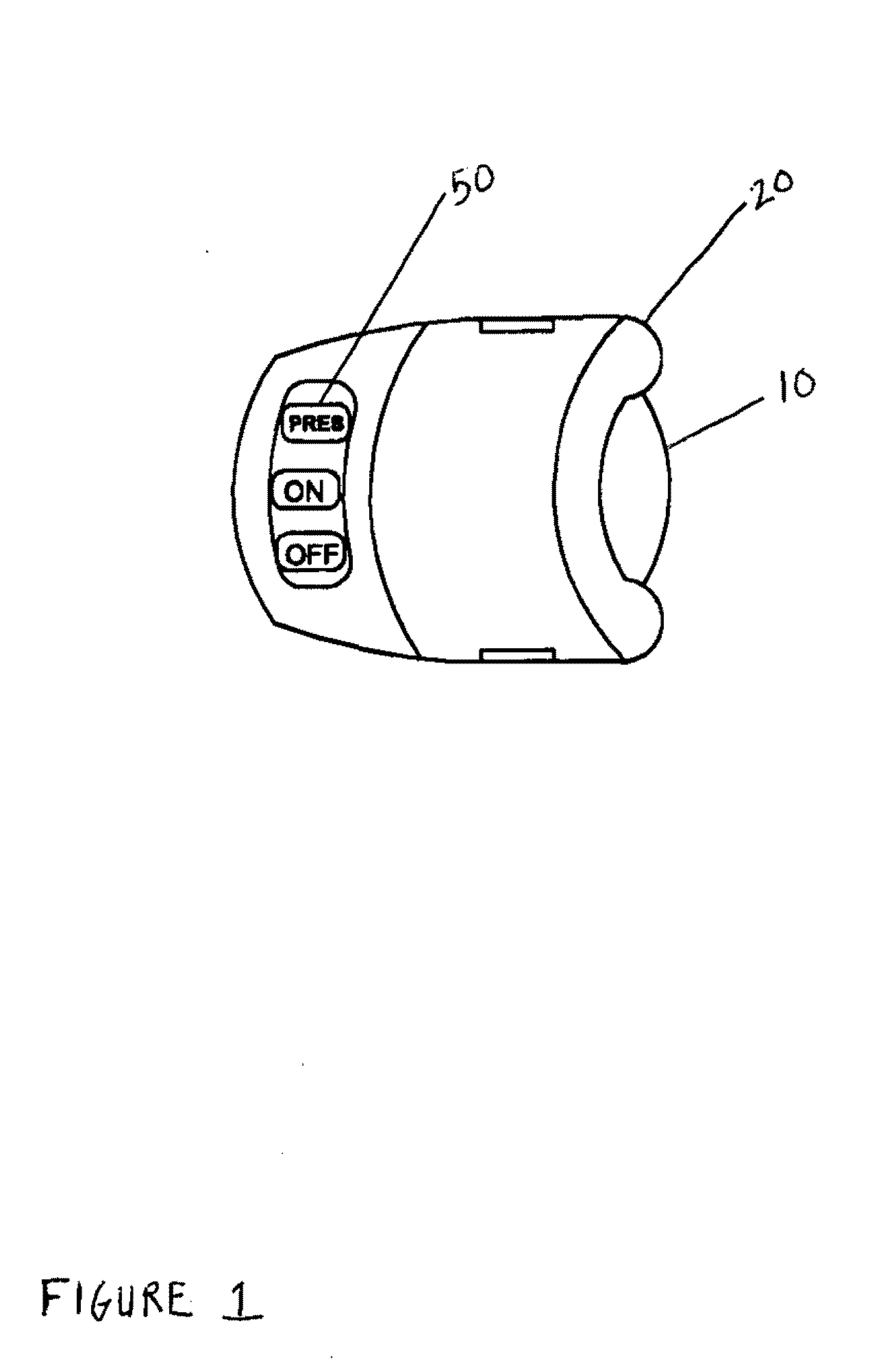
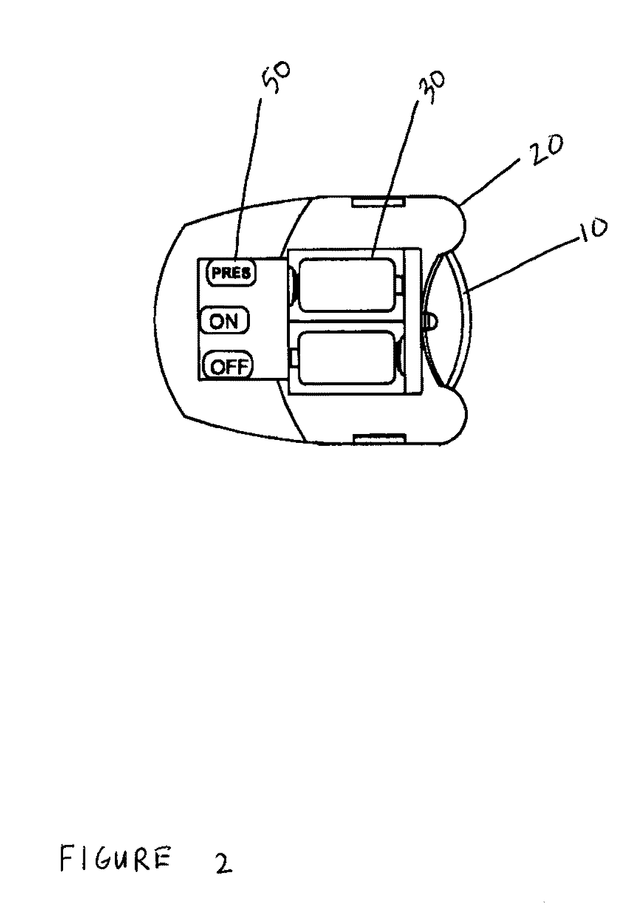
[0026]An exemplary embodiment of a pressure activated lighted glove 200 comprises a glove 100, a light source 10, a means for attaching 20 the light source to the glove, a power source 30 in electrical communication with the light source 10, a pressure sensor 40 attached to the glove 100 that is capable of detecting an applied force, and a pressure sensor bypass means 50. In a preferred exemplary embodiment the utilized glove 100 is both heat and water resistant. An example of such a glove 100 is the Fury Commando glove sold by BLACKHAWK PRODUCTS GROUP. This type of glove 100 is commonly referred to as a tactical glove. Tactical gloves are common and well-known to the art and there are numerous varieties of tactical gloves that could be used in practicing a pressure activated lighted glove 200. In some exemplary embodiments, the outer surface of the glove 100 has been treated with leather or another material to enhance the user's ability to get a grip while wearing the glove. Upon r...


PUM


Abstract

Exemplary embodiments comprise a lighted glove with an infra red light source which can be activated by applying a force to a pressure sensor that is in electrical communication with the light source. Exemplary embodiments are useful in night vision applications.

Description

CROSS REFERENCE TO RELATED APPLICATIONS[0001]This application is a continuation in part of U.S. Ser. No. 12 / 360,580 filed Jan. 27, 2009 which is a non-provisional of U.S. Application No. 61 / 133,082 filed Jun. 26, 2008, each of which are hereby incorporated by reference in their entirety.TECHNICAL FIELD[0002]Exemplary embodiments relate generally to a lighting device. More particularly, embodiments relate to a glove equipped with a light source that can be activated and deactivated through the application of pressure to a pressure sensor that is attached to or located within the glove.BACKGROUND AND SUMMARY OF THE INVENTION[0003]In certain professions and hobbies, individuals must be prepared to handle poorly lit conditions on short notice. Thus, it has become customary for many individuals to carry flashlights on a day to day or at least on a regular basis. Though advances in technology have permitted flashlights to be minimized in size, it is still often inconvenient to juggle a tr...

Claims


Application Information

Patent Timeline
IPC IPC(8): A41D19/00
CPCF21V33/0008A41D19/0157
Inventor MATHENEY, II, TIMOTHY L.THOMPSON, JUSTIN
Owner THOMPSON JUSTIN
Why Eureka
Try Eureka