Airflow driving device having function of measuring flow rate and air conditioner with same

a technology of airflow and driving device, which is applied in the direction of lighting and heating apparatus, domestic cooling apparatus, heating types, etc., can solve the problems of inability to accurately measure the flow rate, failure to effectively remove the heat accumulated in the ambient environment, and the accuracy of estimated airflow is usually undesired, so as to achieve accurate and rapid measurement of the flow rate

Inactive Publication Date: 2011-10-27
DELTA ELECTRONICS INC
View PDF4 Cites 0 Cited by
  • Summary
  • Abstract
  • Description
  • Claims
  • Application Information

AI Technical Summary

Benefits of technology

[0008]Another object of the present invention provides an air conditioner equipped with s

Problems solved by technology

Generally, if the air conditioner has a malfunction or the air conditioner has been used for a long time, the heat accumulated in the ambient environment fails to be effectively removed because the amount of the output airflow is insufficient.
In this situation, the electronic device fails to be normally operated or even damaged.
Although the uses of many air meters are effective to measure the airflow velocities, there are still some drawbacks.
For examp

Method used


Image

  • Airflow driving device having function of measuring flow rate and air conditioner with same
  • Airflow driving device having function of measuring flow rate and air conditioner with same
  • Airflow driving device having function of measuring flow rate and air conditioner with same

Examples


Embodiment Construction

[0014]The present invention will now be described more specifically with reference to the following embodiments. It is to be noted that the following descriptions of preferred embodiments of this invention are presented herein for purpose of illustration and description only. It is not intended to be exhaustive or to be limited to the precise form disclosed.

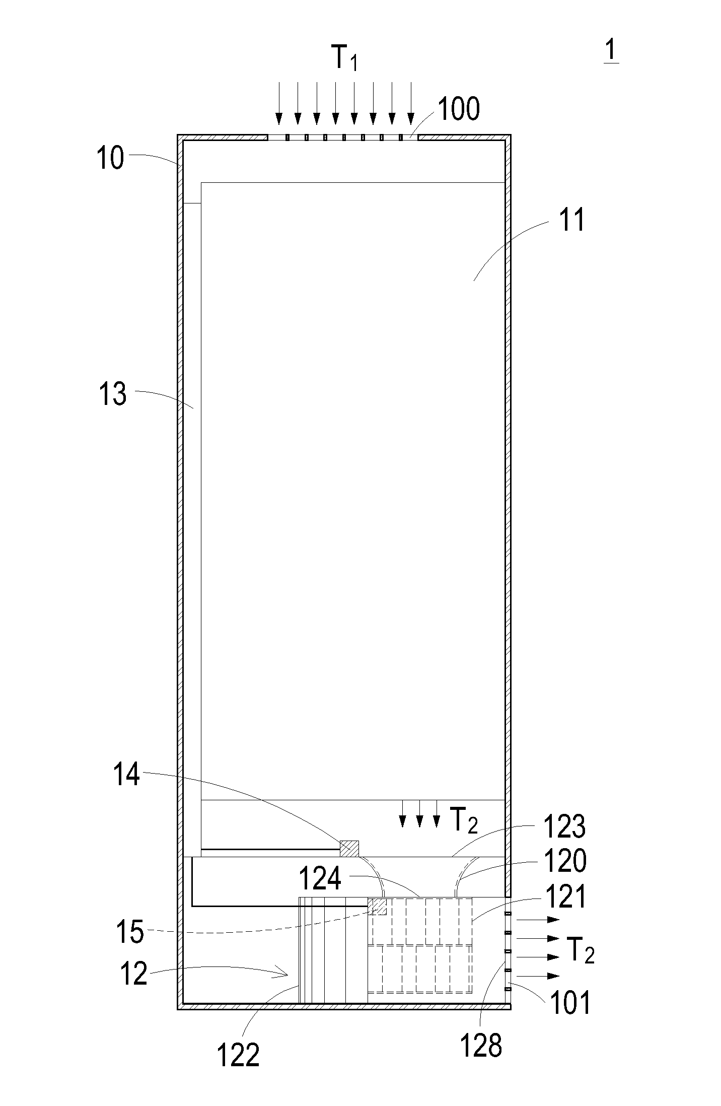
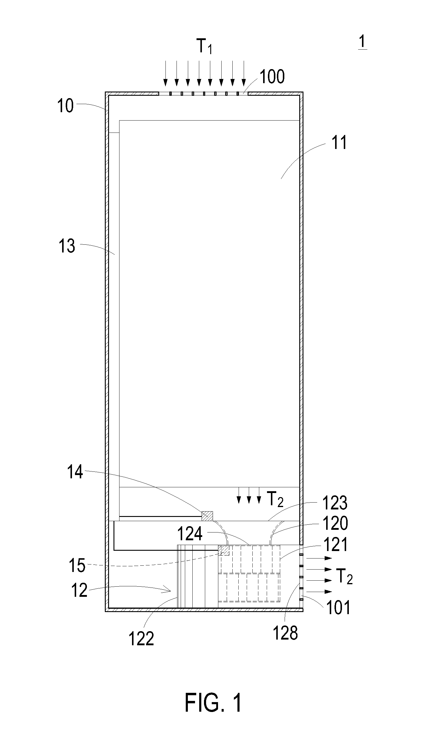
[0015]FIG. 1 is a schematic view illustrating an air conditioner according to an embodiment of the present invention. The air conditioner 1 is used for cooling a first airflow T1 and exhausting a cooled second airflow T2. The air conditioner 1 includes a casing 10, a heat exchanger 11, an airflow driving device 12, a controlling circuit 13, a first pressure-detecting device 14 and a second pressure-detecting device 15. The casing 10 has an inlet 100 and an outlet 101. The first airflow T1 is introduced into the air conditioner 1 through the inlet 100. The second airflow T2 is exhausted out of the air conditioner 1 through the out...


PUM


Abstract

An airflow driving device includes an airflow-guiding member for receiving and guiding an airflow. The airflow-guiding member includes a first opening and a second opening. The open areas of the first opening and the second opening are different such that a pressure difference is generated between the first opening and the second opening. According to the pressure difference, a flow rate of the airflow passing through the airflow driving device is calculated.

Description

FIELD OF THE INVENTION[0001]The present invention relates to an airflow driving device, and more particularly to an airflow driving device having a function of measuring flow rate. The present invention also relates to an air conditioner equipped with such an airflow driving device.BACKGROUND OF THE INVENTION[0002]With rapid development of high-tech industries, various electronic devices such as computer or servers become essential in our lives. As known, the heat-dissipating efficacy of the electronic device influences the operating stability and the use life of the overall system. For increasing the heat-dissipating efficacy of the electronic device, a heat-dissipating mechanism is usually installed within the electronic device or the ambient environment to cool the electronic device.[0003]An air conditioner is one of the common heat-dissipating mechanisms. The air conditioner is usually installed in the ambient environment of the electronic device. During operation of the electro...

Claims


Application Information

Patent Timeline
IPC IPC(8): F25D17/04F25D17/06
CPCF24F11/001F24F2011/0038F24F13/081F24F11/30F24F2110/00F24F2110/30F24F11/74
Inventor HUANG, ZHAO-WEITSOU, YUNG-HUNG
Owner DELTA ELECTRONICS INC
Why Eureka
Try Eureka