Floating impact apparatus for electrical nail gun

a technology of impact apparatus and nail gun, which is applied in the direction of nailing tools, stapling tools, manufacturing tools, etc., can solve the problems of inaccurate nailing position, difficult installation, maintenance, repair, etc., and achieve smooth movement and nailing force, and promote smooth nailing operation and nailing force.

Active Publication Date: 2011-10-27
BASSO IND CORP
View PDF0 Cites 18 Cited by
  • Summary
  • Abstract
  • Description
  • Claims
  • Application Information

AI Technical Summary

Benefits of technology

[0010]The object of this invention is to provide a floating impact apparatus that can promote smooth nail-striking operation and nail-striking force.
[0011]Accordingly, a floating impact apparatus of this invention is used for an electrical nail gun, and includes a carrier, an impact unit, and a floating unit. The impact unit includes an impact member, and at least one sliding wheel disposed pivotally on the impact member. The floating unit includes a guiding rod together with the impact member being connected movably to the carrier, two floating members extending through the carrier to connect with the guiding rod at positions proximate to a first side of the carrier, and at least two resilient members disposed between a second side of the carrier and the floating members for biasing the guiding rod and the impact member to move relative to the carrier to thereby maintain contact between the sliding wheel and the first side of the carrier, so as to promote smooth movement and nail-striking force of the impact member.

Problems solved by technology

However, since the driver is in a suspended state, and is disposed between the follower assembly and the flywheel.
Hence, when the driver is pushed by the follower assembly to contact the flywheel, the end of the driver sways due to application of a pushing force from the follower assembly thereto, thereby resulting in unsmooth movement of the driver, which leads to inaccurate nail-striking position.
Besides, the second conventional electrical nail gun has disadvantages of complicated structure, difficult installation, maintenance, and repair, and high manufacturing costs, and is thus undesirable from an economical standpoint.

Method used


Image

  • Floating impact apparatus for electrical nail gun
  • Floating impact apparatus for electrical nail gun
  • Floating impact apparatus for electrical nail gun

Examples


Embodiment Construction

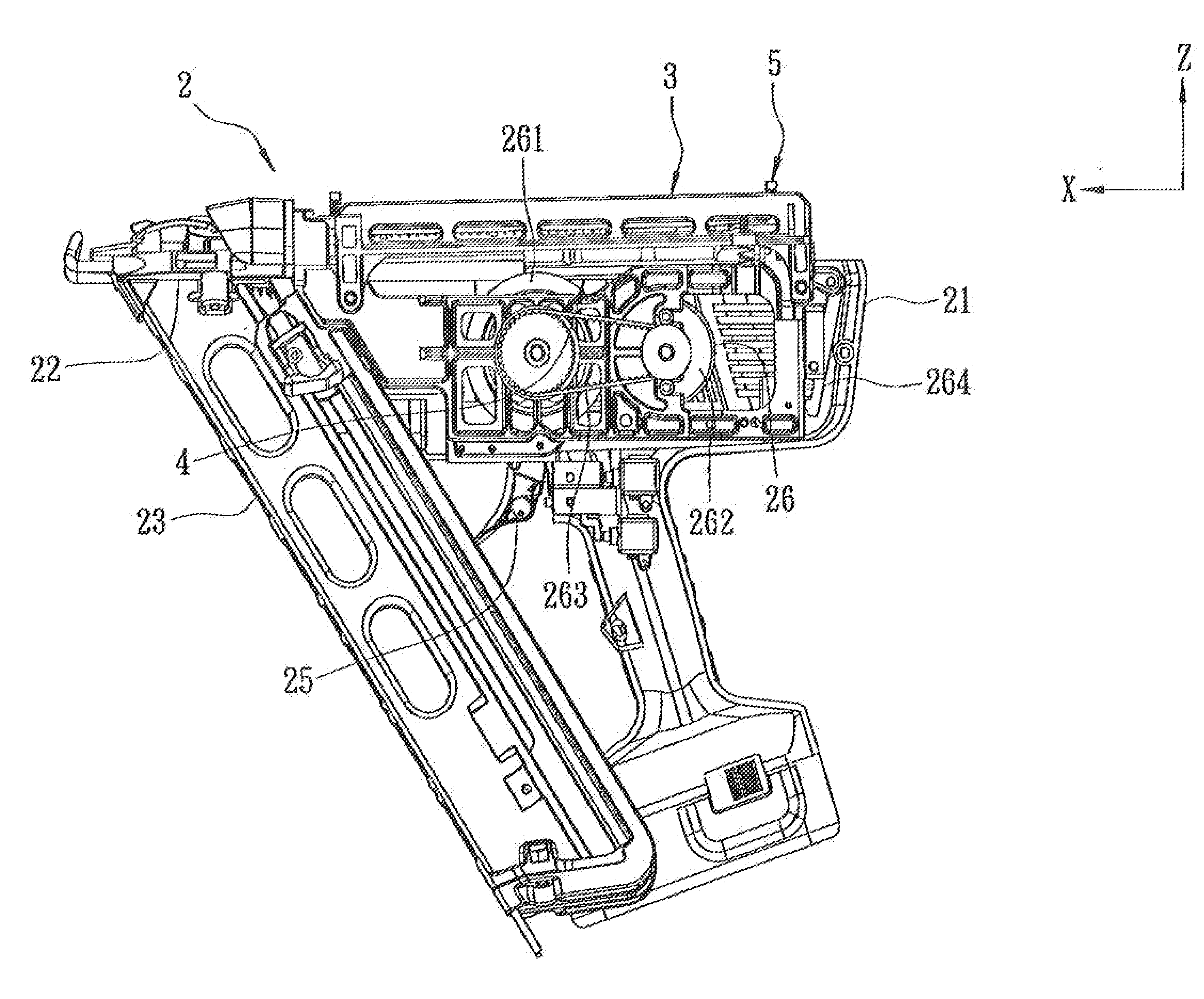
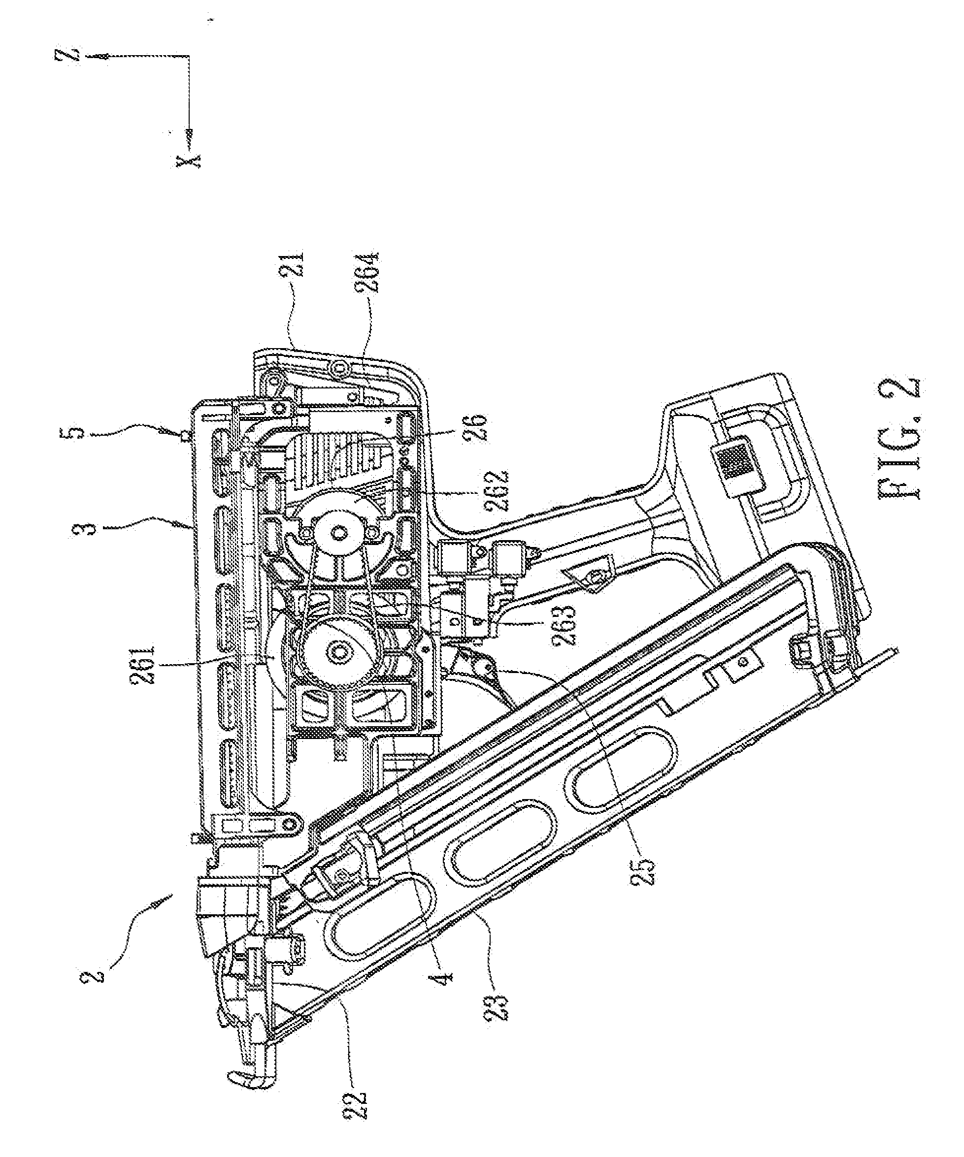
[0019]Referring to FIGS. 2, 3, and 4, the preferred embodiment of a floating impact apparatus according to this invention is mounted to an electrical nail gun 2. The nail gun 2 includes a supporting bracket 21, a nail ejection seat 22 disposed on a front end portion of the supporting bracket 21, a magazine 23 connected to the nail ejection seat 22 for feeding nails (not shown) into the nail ejection seat 22, a striking bar 24 extending through and movable relative to the nail ejection seat 22 along an X-axis direction to impact the nails one at a time, a trigger unit 25 disposed pivotally on the supporting bracket 21 and operable to start a firing operation via a control circuit (not shown), and a transmission unit 26. The transmission unit 26 includes a flywheel 261 disposed pivotally on the supporting bracket 21, a motor 262 adjacent to the flywheel 261 and disposed on the supporting bracket 21, a transmission belt 263 for transmitting power from the motor 262 to the flywheel 261,...


PUM


Abstract

A floating impact apparatus for an electrical nail gun includes a carrier, an impact unit, and a floating unit. The impact unit includes an impact member, and at least one sliding, wheel disposed pivotally on the impact member. The floating unit includes a guiding rod together with the impact member being connected movably to the carrier, two floating members extending through the carrier to connect with the guiding rod at positions proximate to a first side of the carrier, and at least two resilient members disposed between a second side of the carrier and the floating members for biasing the guiding rod and the impact member to move relative to the carrier to thereby maintain contact between the sliding wheel and the first side of the carrier, so as to promote smooth movement and nail-striking force of the impact member.

Description

CROSS-REFERENCE TO RELATED APPLICATION[0001]This application claims priority of Taiwanese Application No. 099113274, filed on Apr. 27, 2010.BACKGROUND OF THE INVENTION[0002]1. Field of the Invention[0003]This invention relates to an electrical nail gun, and more particularly to a floating impact apparatus for an electrical nail gun.[0004]2. Description of the Related Art[0005]Referring to FIG. 1, a first Conventional nail gun 1 disclosed in Taiwanese publication No. 200924918 (corresponding to U.S. Pat. No. 7,575,141) includes a supporting bracket 11, a sliding base 12 movable on the supporting bracket 11 along a nail-striking direction, a swing base 13 disposed pivotally on the supporting bracket 11, an electric driver 14 for driving the swing base 13 to swing relative to the sliding base 12, a motor 15 attached to the swing base 13, and a flywheel 16 driven by the motor 15.[0006]When the motor 15 is energized, it drives the flywheel 16 to rotate. Subsequently, when a trigger unit ...

Claims


Application Information

Patent Timeline
Patent Type & Authority Applications(United States)
IPC IPC(8): B25C5/00
CPCB25F5/006B25C1/06
Inventor CHIEN, CHIA-YUPO, CHIEN-KUOFAN, CHICH-MING
Owner BASSO IND CORP
Why Eureka
Try Eureka