
Slimline tieback connector

a tieback connector and connector technology, applied in the direction of hose connection, hose connection, borehole/well accessories, etc., can solve the problem of relatively large overall diameter of the tieback connector, and achieve the effect of reducing the overall diameter of the connector and evenly dispersing the separation forces

Active Publication Date: 2007-08-09
FMC TECH INC
View PDF19 Cites 12 Cited by
  • Summary
  • Abstract
  • Description
  • Claims
  • Application Information

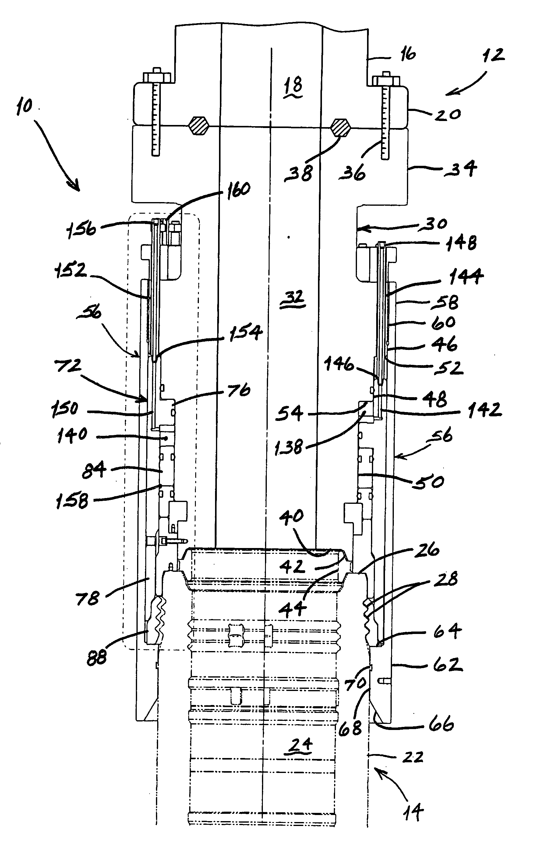
AI Technical Summary

Benefits of technology

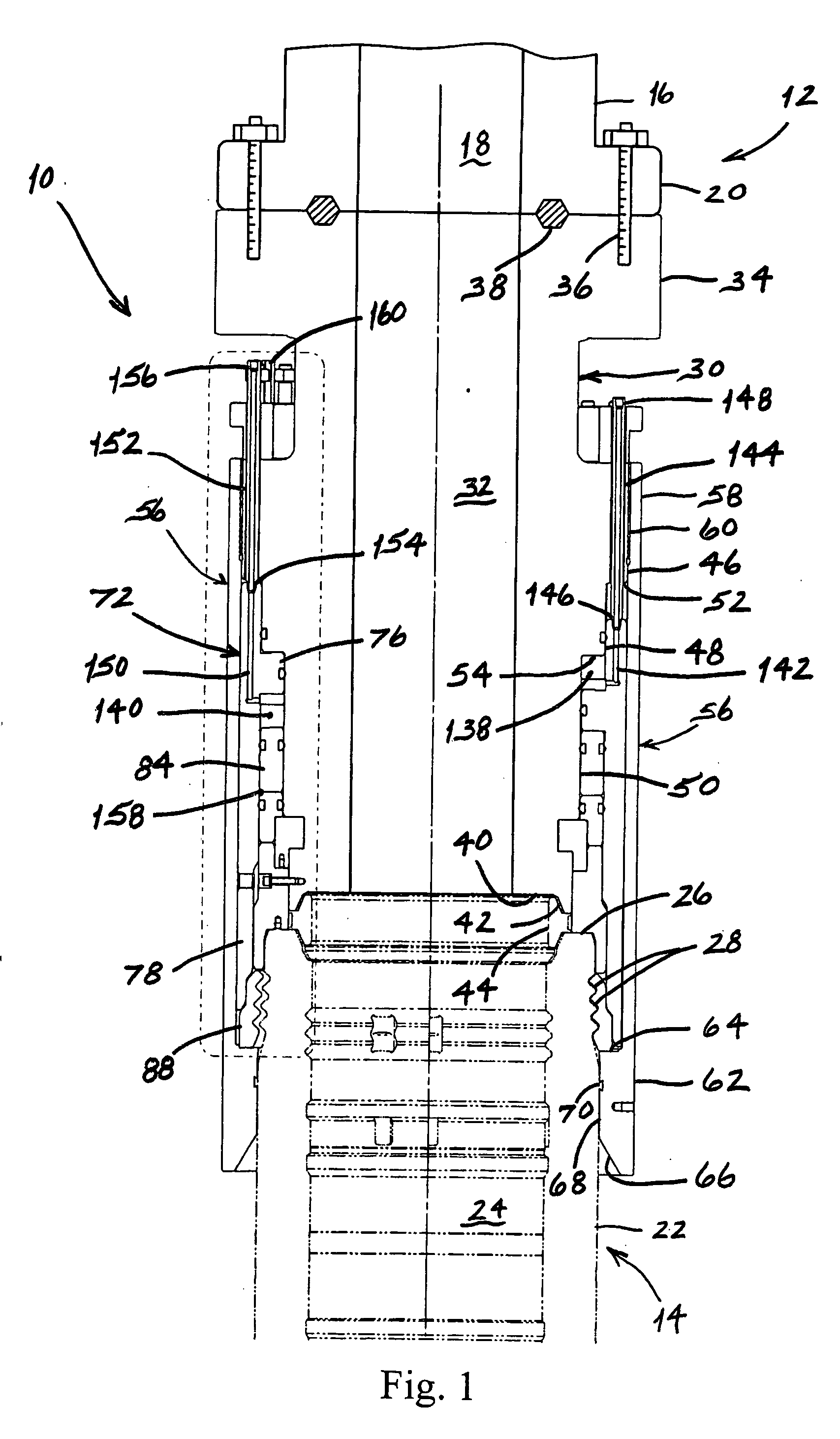
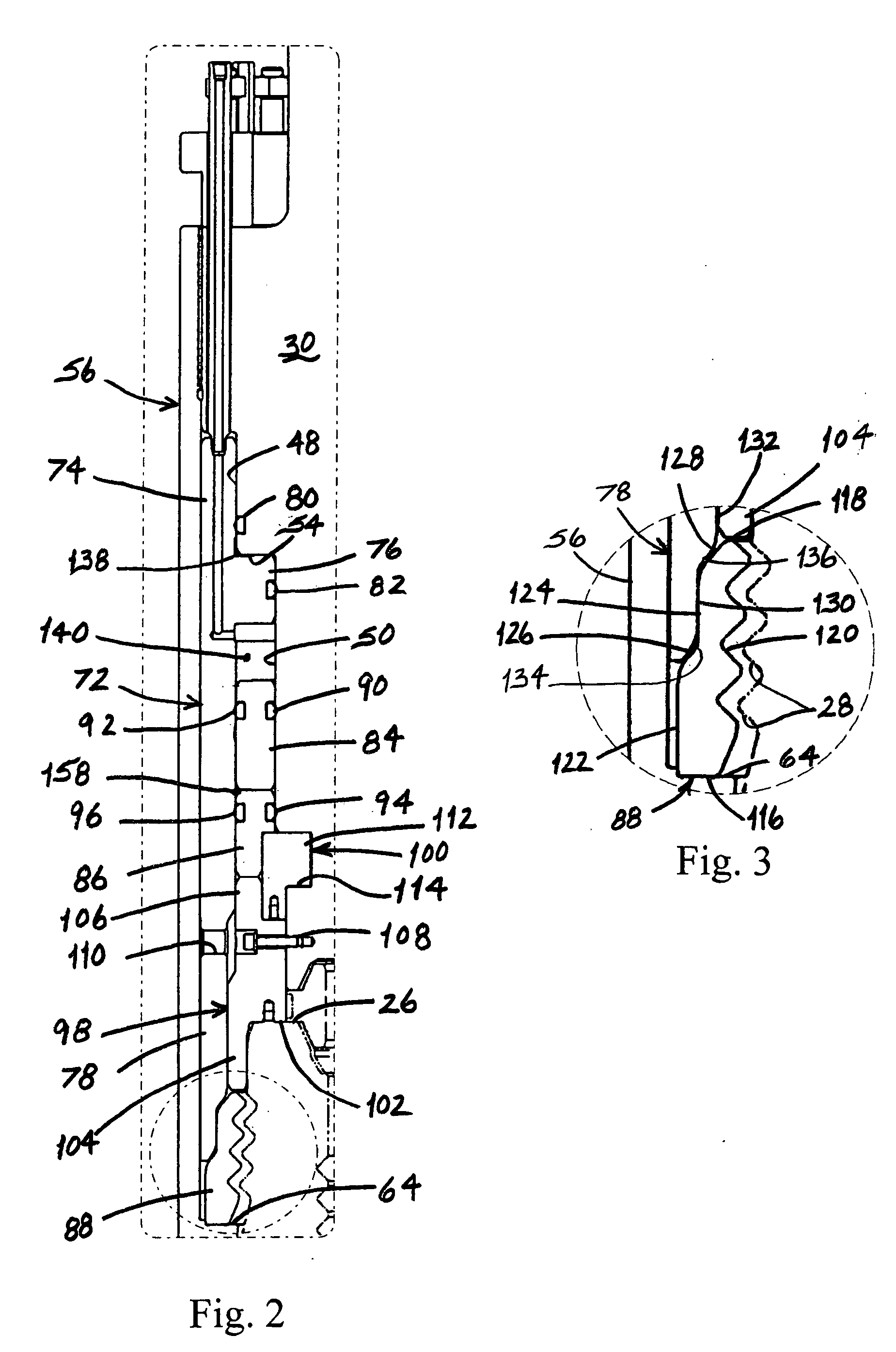
[0004] Thus, when the connector is locked to the second member, the stepped interface between the locking mandrel and the lock ring provides two distinct bearing surfaces through which separation forces acting between the first and second members are transmitted. In addition, the provision of these two distinct bearing surfaces tends to distribute the separation forces more evenly among all the locking grooves compared to prior art designs. Consequently, for a given anticipated set of separation forces, the overall diameter of the connector can be reduced.

Problems solved by technology

Since the production riser extends to a surface vessel which is located a considerable distance from the wellhead, the production riser is typically subjected to sizeable forces which give rise to substantial separation forces between the tieback connector and the wellhead.
However, this in turn required the overall diameter of the tieback connector to be relatively large, which is undesirable when working from certain types of surface vessels.

Method used


Image

  • Slimline tieback connector
  • Slimline tieback connector
  • Slimline tieback connector

Examples


Embodiment Construction

[0010] The slimline tieback connector of the present invention provides a simple yet effective means for remotely connecting two subsea hydrocarbon production members together. Although the slimline tieback connector can be used to connect any of a variety of subsea hydrocarbon production members, it is particularly useful for securing a first generally cylindrical member to a second generally cylindrical member in an end-to-end arrangement. For purposes of simplicity, however, the present invention will be described herein in the context of a connector for securing a production riser to a subsea welihead.

[0011] Referring to FIG. 1, the tieback connector of the present invention, which is indicated generally by reference number 10, is shown being used to secure a slimline production riser 12 to an exemplary subsea wellhead 14. The production riser 12 comprises a generally cylindrical riser body 16, a production bore 18 which extends axially through the riser body, and a bottom conn...


PUM


Abstract

A connector for securing a first cylindrical member to a second cylindrical member comprises a cylindrical body which includes a first end that is attached to the first member and a second end that is positioned proximate the second member, a cylindrical housing sleeve which is positioned concentrically over the body and which includes an upper end portion that is secured to the body and a lower end portion that is disposed adjacent the second member, a cylindrical primary piston that is positioned between the body and the housing sleeve, a locking mandrel which is connected to or formed integrally with the primary piston and which includes at least first and second annular portions that have different diameters, and a split lock ring which is supported by the lower end portion adjacent a number of locking grooves in the second member and which includes at least first and second cylindrical portions that correspond to the first and second annular portions of the locking mandrel. In operation, movement of the primary piston from a first position to a second position will force the first and second annular portions of the locking mandrel into engagement with the first and second cylindrical portions of the lock ring, respectively, and consequently force the lock ring into engagement with the locking grooves to thereby lock the connector to the second member.

Description

BACKGROUND OF THE INVENTION [0001] The present invention relates to a connector for securing a first generally cylindrical member, such as a production riser, to a second generally cylindrical member, such as a subsea wellhead. More particularly, the invention relates to a connector which comprises a locking mandrel that includes a stepped surface which engages a corresponding stepped surface on a lock ring to thereby force the lock ring into locking engagement with the second member. [0002] Tieback connectors are commonly used to secure production risers to subsea wellheads. Since the production riser extends to a surface vessel which is located a considerable distance from the wellhead, the production riser is typically subjected to sizeable forces which give rise to substantial separation forces between the tieback connector and the wellhead. Thus, the tieback connector must be able to maintain a sealed connection to the wellhead in the presence of these separation forces. In the...

Claims


Application Information

Patent Timeline
IPC IPC(8): E21B33/00
CPCE21B33/038
Inventor SINGEETHAM, SHIVABALTMANIS, ERIC
Owner FMC TECH INC
Learn More