Electronic method to improve the starting characteristics of direct current arc lamps

a technology of arc lamps and starting characteristics, applied in the field of electronic methods to improve the starting characteristics of arc lamps, can solve the problem of lamps not igniting 100

Inactive Publication Date: 2011-10-27
WARNER POWER
View PDF2 Cites 0 Cited by
  • Summary
  • Abstract
  • Description
  • Claims
  • Application Information

AI Technical Summary

Benefits of technology

The present invention features a starting circuit for an arc lamp. The starting circuit comprises a series coupled L-C resonant circuit, a first end of said series coupled L-C resonant circuit is connected between a first lamp electrode and a chassis ground. A source of a high voltage impulse is coupled to the first lamp electrode and the first end of the series L-C resonant circuit, wherein the high voltage impulse is configured to energize the L-C resonant circuit, thereby causing the L-C resonant circuit to extend a tail of said high voltage impulse with a series of high frequency oscillations, wherein the tail is configured to cause a plasma streamer to remain in an ionized state for period of time which is greater than a period of time the plasma streamer would remain in an ionized state without the series L-C resonant circuit, at least until a current ramp in the arc lamp up occurs.
The invention also features a method of starting a direct current arc lamp, such as an Xenon arc lamp, the method comprises the acts of connecting a series coupled L-C resonant circuit between a first lamp electrode and a chassis ground, wherein the series connected L-C resonant circuit is configured to store energy and act as an oscillator. The method next includes energizing the series coupled L-C resonant circuit with an initial high voltage impulse, wherein the series coupled L-C resonant circuit is configured to extend a tail or end of the initial high voltage impulse with a plurality of high frequency oscillations, wherein the plurality of high frequency oscillations is configured to cause a plasma streamer in said xenon arc lamp to remain in an ionized state for an extended time until a current ramp up occurs.

Problems solved by technology

This delay may cause intermittent misfiring of the lamp causing the lamp to not ignite 100% of the time.

Method used


Image

  • Electronic method to improve the starting characteristics of direct current arc lamps
  • Electronic method to improve the starting characteristics of direct current arc lamps

Examples


Embodiment Construction

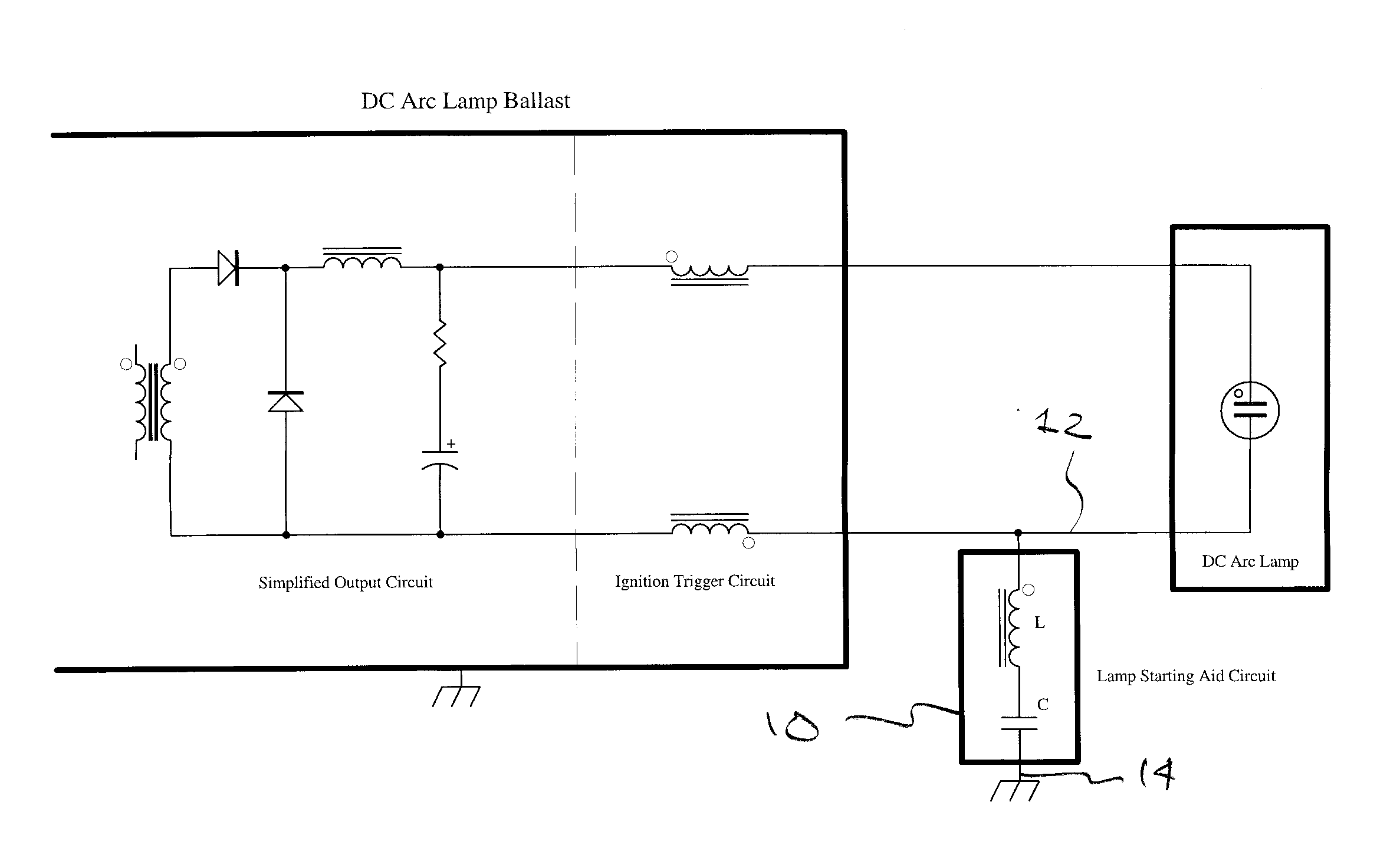
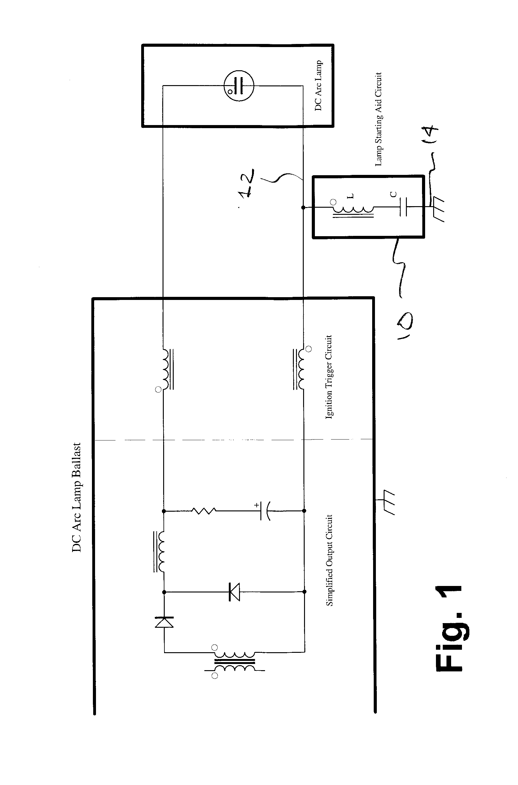
The invention utilizes a simple L-C resonant circuit 10, FIG. 1, connected between a lamp electrode 12 to chassis ground 14. This circuit 10 has the ability to store energy as well as act as an oscillator. Energized by an initial high voltage pulse applied to the lamp electrode 12, this circuit extends the ‘tail’ or end of the voltage pulse with a train or series of high frequency (in the range of 1 Mhz) oscillations, which gradually decay. An exemplary circuit 10 including a capacitor having a value of 3300 pF and an inductor or ignition core having a value of 15 T an F.A. has proved satisfactory. This resonant ‘tail’ causes the plasma streamer in the lamp to remain in the ionized state for an extended time, until the current ramp up occurs that will keep the lamp ignited. This results in highly reliable ignition.

As mentioned above, the present invention is not intended to be limited to a device or method which must satisfy one or more of any stated or implied objects or features o...


PUM


Abstract

A series connected L-C resonant circuit is connected between a lamp electrode of a xenon arc lamp and chassis ground. The L-C circuit has the ability to store energy as well as act as an oscillator. Energized by an initial high voltage pulse to a xenon arc lamp, the L-C circuit extends the ‘tail’ of the initial high voltage pulse provided to ignite the xenon arc lamp with a train or series of high frequency oscillations, which gradually decay. This resonant ‘tail’ causes the plasma streamer in the lamp to remain in the ionized state for an extended time period, until current ramp to the lamp up occurs, resulting in highly reliable ignition of the xenon arc lamp.

Description

TECHNICAL FIELDThe present invention relates to DC arc lamps and more particularly, to a method for improving the starting circuit for such DC arc lamps such as Xenon arc lamps.BACKGROUNDDC arc lamps such as a xenon arc lamp requires a very brief high voltage pulse, typically 20 kV or higher, to create an initial ‘streamer’ of ionized gas between the cathode and anode of the lamp. This creates a conductive path of charge-carrying ions. Following this pulse, and before the ionization naturally decays due to recombination of ions, the direct current supplied to the lamp, at low voltage, must be ramped up quickly, but in a controlled manner. This increasing current sustains the ionization and develops the initial streamer into a full scale arc. Once the full arc is achieved, the lamp is supplied in a constant-current mode, to ensure stable operation and to avoid over-driving the lamp.It is highly desirable, in many critical applications, that lamps ignite 100% reliably each time that i...

Claims


Application Information

Patent Timeline
Patent Type & Authority Applications(United States)
IPC IPC(8): H05B41/233
CPCH05B41/2881Y02B20/204H05B41/388Y02B20/00
Inventor SWIDEREK, STANISLAW W.
Owner WARNER POWER
Why Eureka
Try Eureka