Brake Resistor Control

Active Publication Date: 2011-10-27
DEERE & CO
View PDF7 Cites 12 Cited by
  • Summary
  • Abstract
  • Description
  • Claims
  • Application Information

AI Technical Summary

Benefits of technology

[0009]Such a brake resistor control scheme promotes energy efficiency through optimization of brake resistor usage. It offers the opportunity to operate the brake resistor at an intermediate brake duty rather than only constant ON and constant OFF. Further, it considers the amount of power desired to be consumed. In so doing, the brake resisto

Problems solved by technology

From an energy efficiency point of view, the prior art PI-based voltage control scheme assisted by hysteretic brake resistor control does

Method used


Image

  • Brake Resistor Control
  • Brake Resistor Control
  • Brake Resistor Control

Examples


Example

DETAILED DESCRIPTION OF THE DRAWINGS

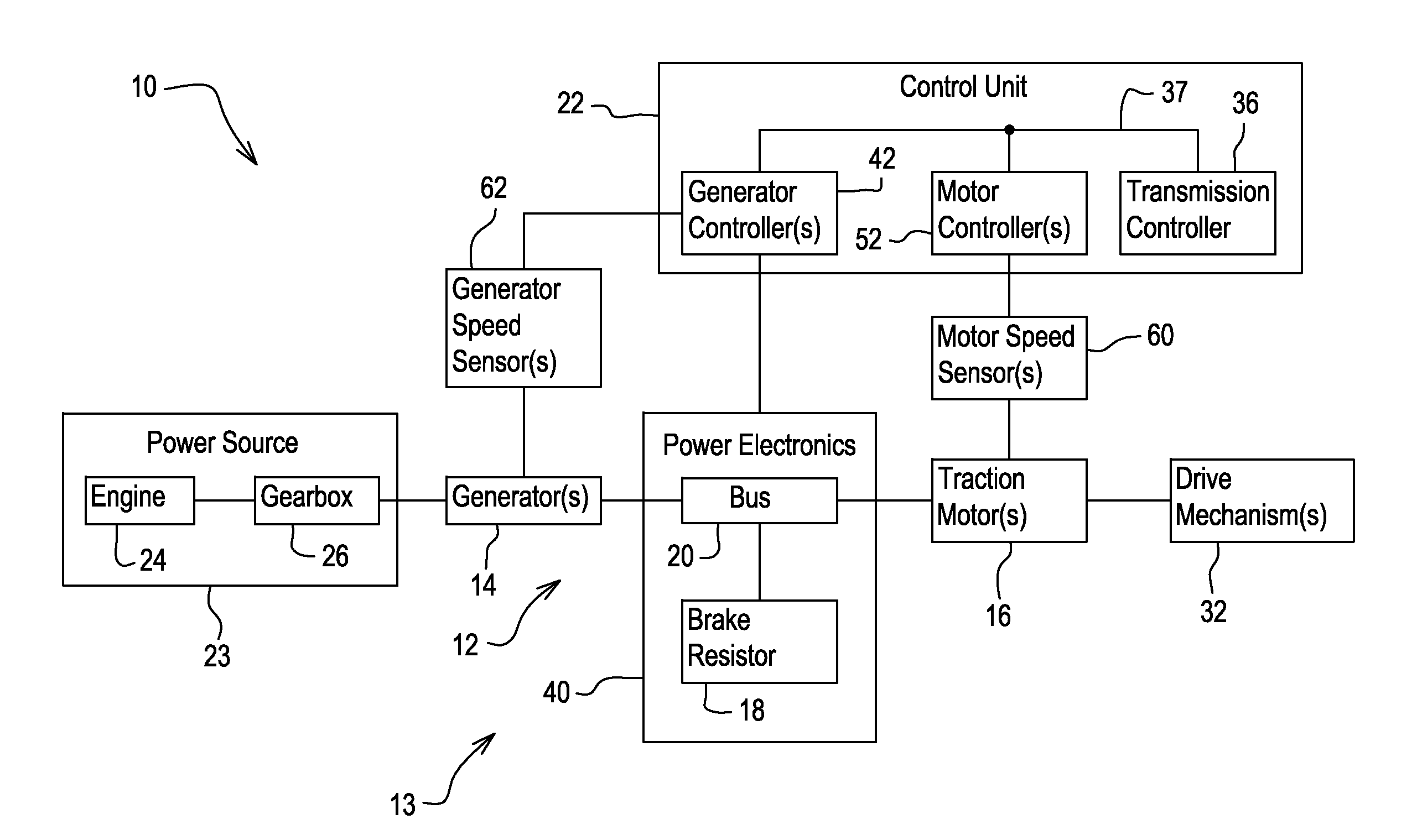
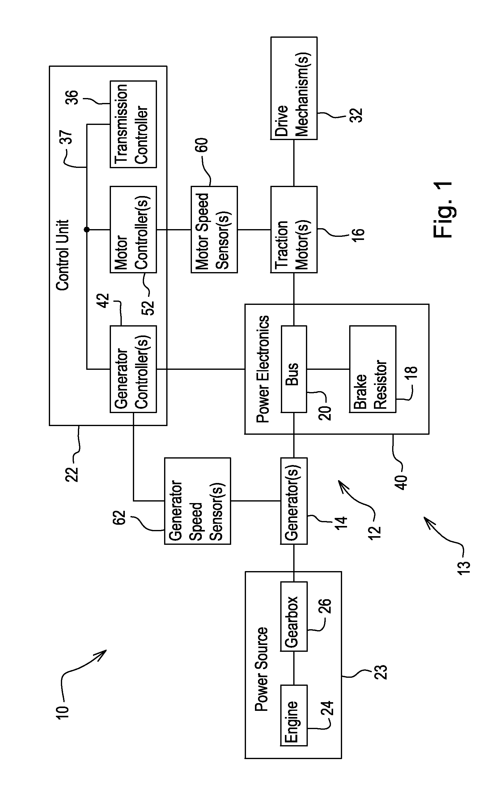
[0017]Referring to FIG. 1, there is shown diagrammatically a series hybrid vehicle 10 having an electric drive system 12 of a power train 13 of the vehicle 10. The vehicle 10 may be a work vehicle (e.g., construction, forestry, agriculture, turf, to name but a few) or any other type of vehicle having an electric drive system. By way of example, the vehicle 10 may be a four-wheel drive loader having a front section and a rear section articulated to the front section, the front section having, for example, a bucket for digging and dumping material, the rear section having, for example, the operator's station and the engine compartment rearward thereof.

[0018]The electric drive system 12 has a generator 14, a traction motor 16, a brake resistor 18, a bus 20 (e.g., a DC bus), and a control unit 22. The generator 14, the traction motor 16, and the brake resistor 18 may be coupled electrically to the bus 20. The control unit 22 may be configured to deter...


PUM


Abstract

An electric drive system comprises a generator, a traction motor, a brake resistor, a bus, and a control unit. The generator, the traction motor, and the brake resistor are coupled electrically to the bus. The control unit is configured to determine a pulse-width-modulation duty cycle for the brake resistor (“brake duty”) and control operation of the brake resistor according to the brake duty, wherein the brake duty can be a value intermediate of constant OFF and constant ON. A method of operating the electric drive system is also disclosed.

Description

FIELD OF THE DISCLOSURE[0001]The present disclosure relates to an electric drive system such as on a hybrid vehicle. In particular, the present disclosure relates to control of a brake resistor.BACKGROUND OF THE DISCLOSURE[0002]In some series hybrid vehicles, the vehicle has an internal combustion engine, a generator, a traction motor, a brake resistor, and a DC bus (“DC” means direct current) to which the generator, the traction motor, and the brake resistor are electrically coupled. The generator converts mechanical energy from the engine into electric energy on the bus and can operate in the opposite direction to convert electric energy from the bus into mechanical energy to assist the engine with other functions on board the vehicle (e.g., raising a bucket hydraulically). The traction motor converts electric energy from the bus into mechanical energy for use in driving one or more traction elements (e.g., ground-engaging wheels) (“motoring”) and can operate in the opposite direc...

Claims


Application Information

Patent Timeline
IPC IPC(8): H02P3/12B60L50/13B60L50/15
CPCH02P3/22B60L7/02Y02T10/70Y02T10/7077Y02T10/642B60L11/10B60L50/14Y02T10/64Y02T10/7072B60K6/26B60L7/22H02P27/06
Inventor VILAR, ZIMIN W.
Owner DEERE & CO
Why Eureka
Try Eureka