
Convolutional code for use in a communication system

a communication system and code technology, applied in the field of ultrawideband communication systems, to avoid unnecessary proliferation of numbers

Active Publication Date: 2011-10-27
DECAWAVE
View PDF13 Cites 4 Cited by
  • Summary
  • Abstract
  • Description
  • Claims
  • Application Information

AI Technical Summary

Benefits of technology

The invention provides a communication system that uses a transmitter and a receiver to transmit and detect bits of information. The transmitter generates a code based on the input bit and sends it to the receiver. The receiver has multiple detectors that each detect a bit generated by one of the same generators. The detectors provide partial detection signals if the bit strength exceeds a minimum threshold. A majority logic element combines the partial detection signals to produce the output bit, which indicates the input bit only if more than a certain number of the detectors exceed the minimum threshold. This invention allows for more efficient and accurate communication between devices.

Problems solved by technology

Furthermore, it is of no relevance in such systems which specific voltage levels are selected to represent each of the logic states.

Method used


Image

  • Convolutional code for use in a communication system
  • Convolutional code for use in a communication system
  • Convolutional code for use in a communication system

Examples


Embodiment Construction

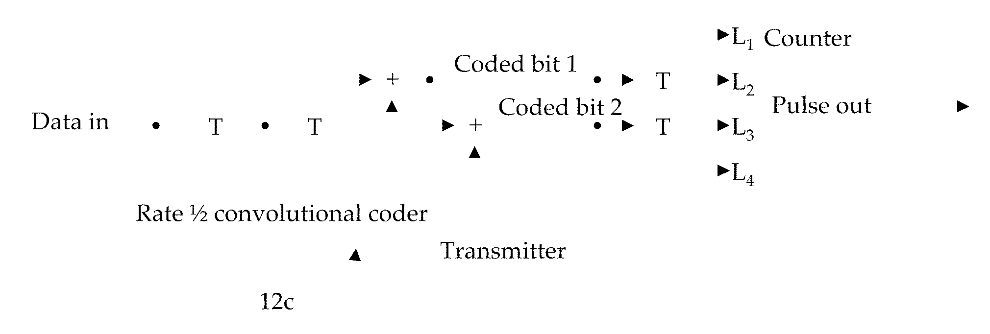
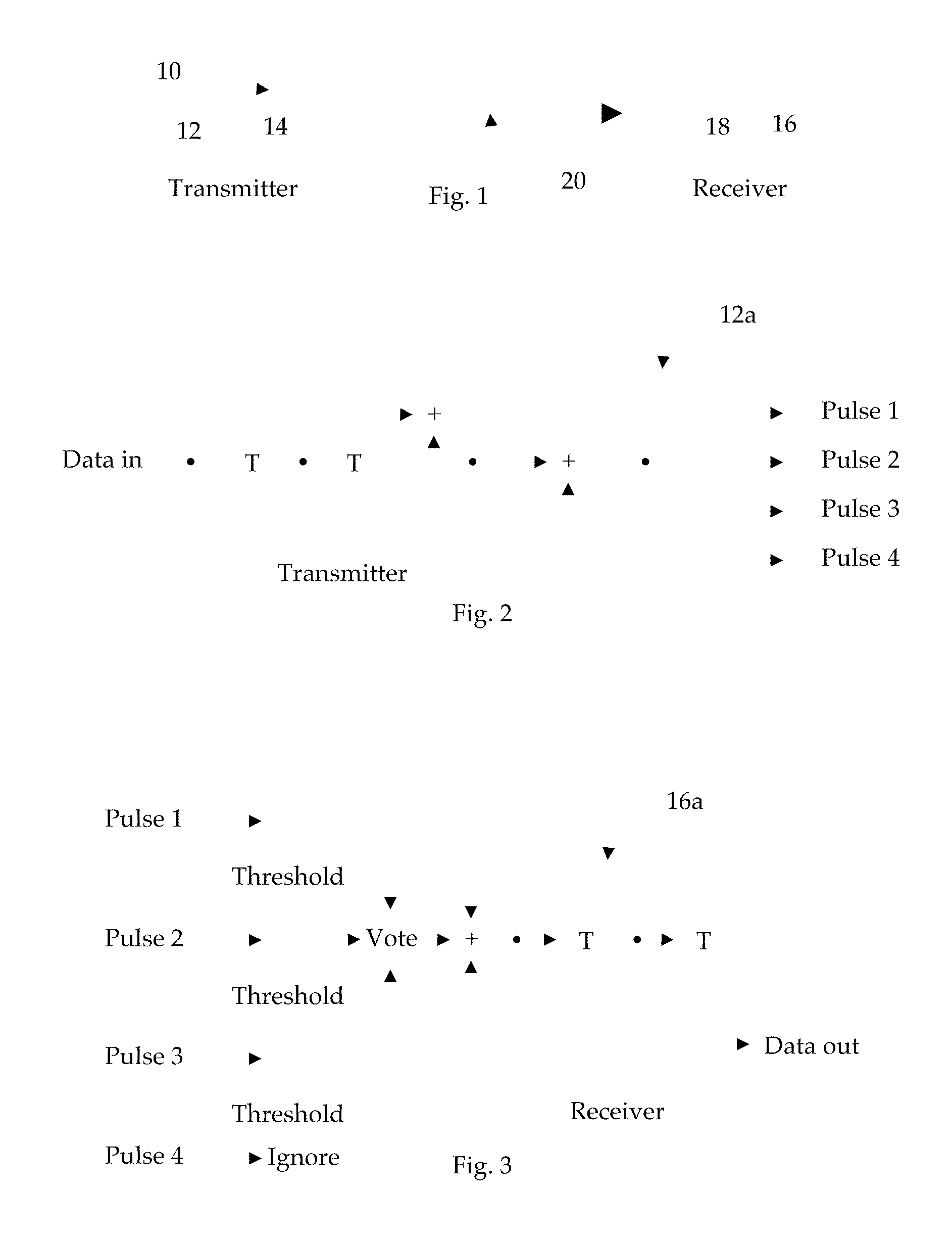
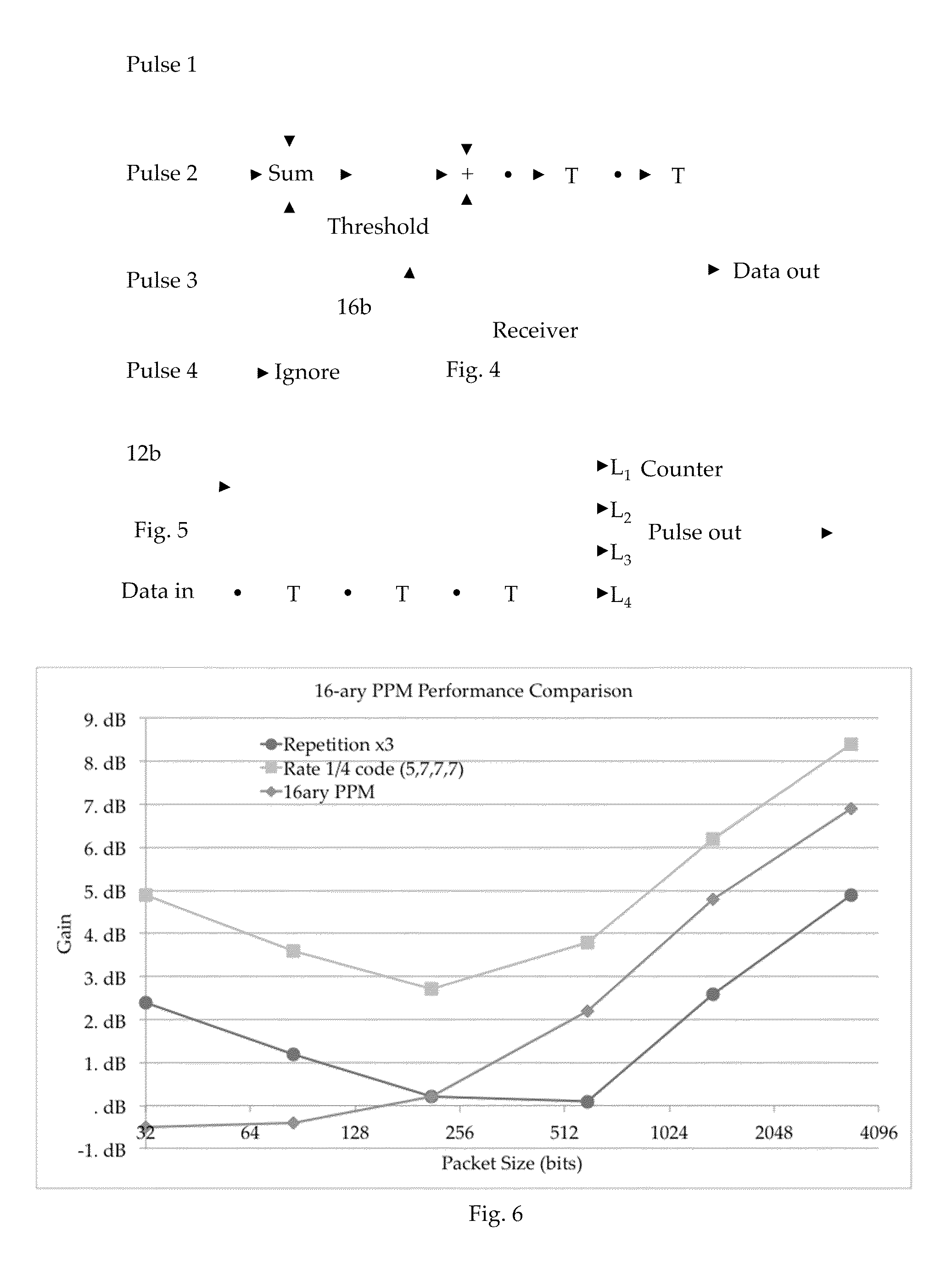
[0036]Shown in FIG. 1 is a communication system 10 constructed in accordance with our invention. In general, communication system 10 comprises a transmitter 12 having a transmitting antenna 14, and a receiver 16 having a receiving antenna 18. During normal operation, transmitter 12 transmits a signal to receiver 16 via antennas 14 and 18, as generally indicated by dashed line 20. In one embodiment of our invention, transmitter 12 and receiver 16 operate using ultra-wide-band technologies as explained hereinafter (see, also, the Related Patents and Related Applications). In accordance with our invention, transmitter 12 is adapted to receive each of a plurality of input bits, and in response to receiving each such bit, to generate a respective codeword comprising at least n-bits, each bit of which is generated by a respective one of n generators of which m are exactly the same, m being greater than n / 2. As is known, the bits comprising each codeword are generated in parallel, but ther...


PUM


Abstract

In a communication system, a transmitter receives an input bit, and in response thereto, generates at least an n-bit codeword, each bit of which is generated by a respective one of n generators of which m are exactly the same, m being greater than n / 2. A receiver comprises: m detectors, each adapted to receive the bit generated by a respective one of the m generators, and provide a respective one of m partial detection signals if a strength of the received bit exceeds a predetermined minimum threshold; and a majority logic element adapted to receive each of the m partial detection signals, and provide an output bit indicative of the input bit only if more than m / 2 of the received m partial detection signals exceeds the minimum threshold.

Description

CROSS-REFERENCE TO RELATED APPLICATIONS[0001]This application claims priority to U.S. Provisional Patent Applications Ser. No. 61 / 332,126, filed 6 May 2010, Ser. No. 61 / 327,769, filed 26 Apr. 2010, and Ser. No. 61 / 326,282, filed 21 Apr. 2010 (“Parent Provisional(s)”). The forgoing Parent Provisional is hereby incorporated by reference in its entirety as if fully set forth herein.BACKGROUND OF THE INVENTION[0002]1. Field of the Invention[0003]The present invention relates generally to ultra-wideband communication systems, and, in particular, to a convolutional code for use in a communication system.[0004]2. Description of the Related Art[0005]In general, in the descriptions that follow, we will italicize the first occurrence of each special term of art, which should be familiar to those skilled in the art of ultra-wideband (“UWB”) communication systems. In addition, when we first introduce a term that we believe to be new or that we will use in a context that we believe to be new, we...

Claims


Application Information

Patent Timeline
Patent Type & Authority Applications(United States)
IPC IPC(8): H03M13/03G06F11/10
CPCH03M13/23H03M13/3769H03M13/41H04L1/08H03M13/655H04L1/0054H03M13/6306
Inventor MCLAUGHLIN, MICHAELVERSO, BILLY
Owner DECAWAVE
Learn More