Video speed detection system

a speed detection and video technology, applied in the field of vehicle speed measurement, can solve the problem of not being able to reproduce the speed of the vehicle based on which the citation is issued

Active Publication Date: 2011-11-03
AMERICAN TRAFFIC SOLUTIONS
View PDF7 Cites 44 Cited by
  • Summary
  • Abstract
  • Description
  • Claims
  • Application Information

AI Technical Summary

Benefits of technology

[0010]As discussed above, in modern automated speed law enforcement, a speed measuring device is often supplemented with enforcement cameras that take photographs of speeding vehicles. The device measures vehicle speeds and triggers the enforcement camera(s) to take photographs of vehicles traveling above a predetermined speed limit. However, while the recorded photographs can be used to identify the registered owner or even the driver of the offending vehicle, they can not be used to reproduce the speed of the vehicle based on which the citation is issued. Therefore, it is of immense advantage to have a system that is not only capable of accurately measuring vehicle speeds in real time but also is capable of reproducing the vehicle speeds from recorded video evidence.
[0011]Accordingly, aspects and embodiments are directed to a system that can both accurately measure vehicle speeds in real time and reproduce the vehicle speeds either manually or automatically from the recorded video evidence. According to one embodiment, the system comprises a tracking camera and a processing unit. The tracking camera is capable of generating accurately time-stamped images of the monitored road and streaming them to the processing unit at a high frame rate. The processing unit processes each frame it receives from the tracking camera to detect and identifies moving vehicles, and continues to track the detected vehicles through subsequent frames until the vehicles exit the tracking camera's field of view. According to one embodiment, the system allows an operator to mark four reference points on the road surface to define a parallelogram zone. It then establishes the projective mapping between image coordinates and real-world coordinates from the four point correspondences. While the system tracks detected vehicles as they pass through the monitored road segment, it keeps updating the vehicles' position information by projecting their image coordinates back into real-world coordinates, and extracts time information from the date and time stamp associated with each image frame. The system then calculates a vehicle's speed by dividing the distance the vehicle travels by the time it spends to cover the corresponding distance. As a vehicle exits the monitored zone, the system compares its exit speed to the trigger speed set by the operator and triggers the tracking camera to record a video clip showing the vehicle entering and leaving the camera's field of view. In addition, the system can trigger supplemental high-resolution cameras to take photographs of the speeding vehicle so that the registration or driver information of the vehicle can be obtained. With the recorded time-stamped video clip, the speed of a vehicle can be reproduced using the same algorithm offline, or a speed estimate can be generated manually from the time-stamped video using the basic time-over-distance method.

Problems solved by technology

However, while the recorded photographs can be used to identify the registered owner or even the driver of the offending vehicle, they can not be used to reproduce the speed of the vehicle based on which the citation is issued.

Method used


Image

  • Video speed detection system
  • Video speed detection system
  • Video speed detection system

Examples


Embodiment Construction

[0039]This invention is not limited in its application to the details of construction and the arrangement of components set forth in the following description or illustrated in the drawings. The invention is capable of implementation in other embodiments and of being practiced or of being carried out in various ways. Examples of specific implementations are provided herein for illustrative purposes only and are not intended to be limiting. In particular, acts, elements and features discussed in connection with any one or more embodiments are not intended to be excluded from a similar role in any other embodiments. In addition, it is to be appreciated that the phraseology and terminology used herein is for the purpose of description and should not be regarded as limiting. The use herein of “including,”“comprising,”“having,”“containing,”“involving,” and variations thereof is meant to encompass the items listed thereafter and equivalents thereof as well as additional items.
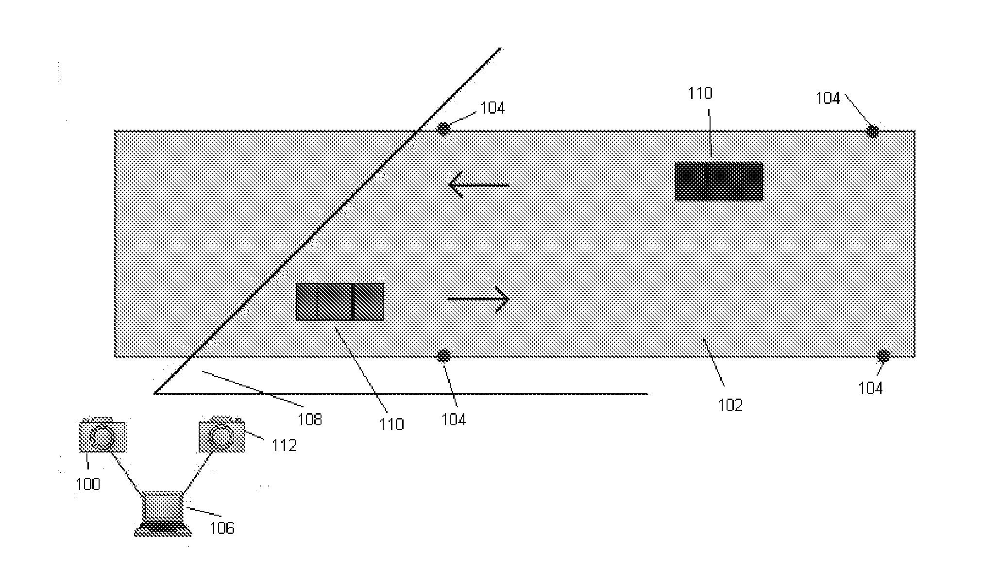
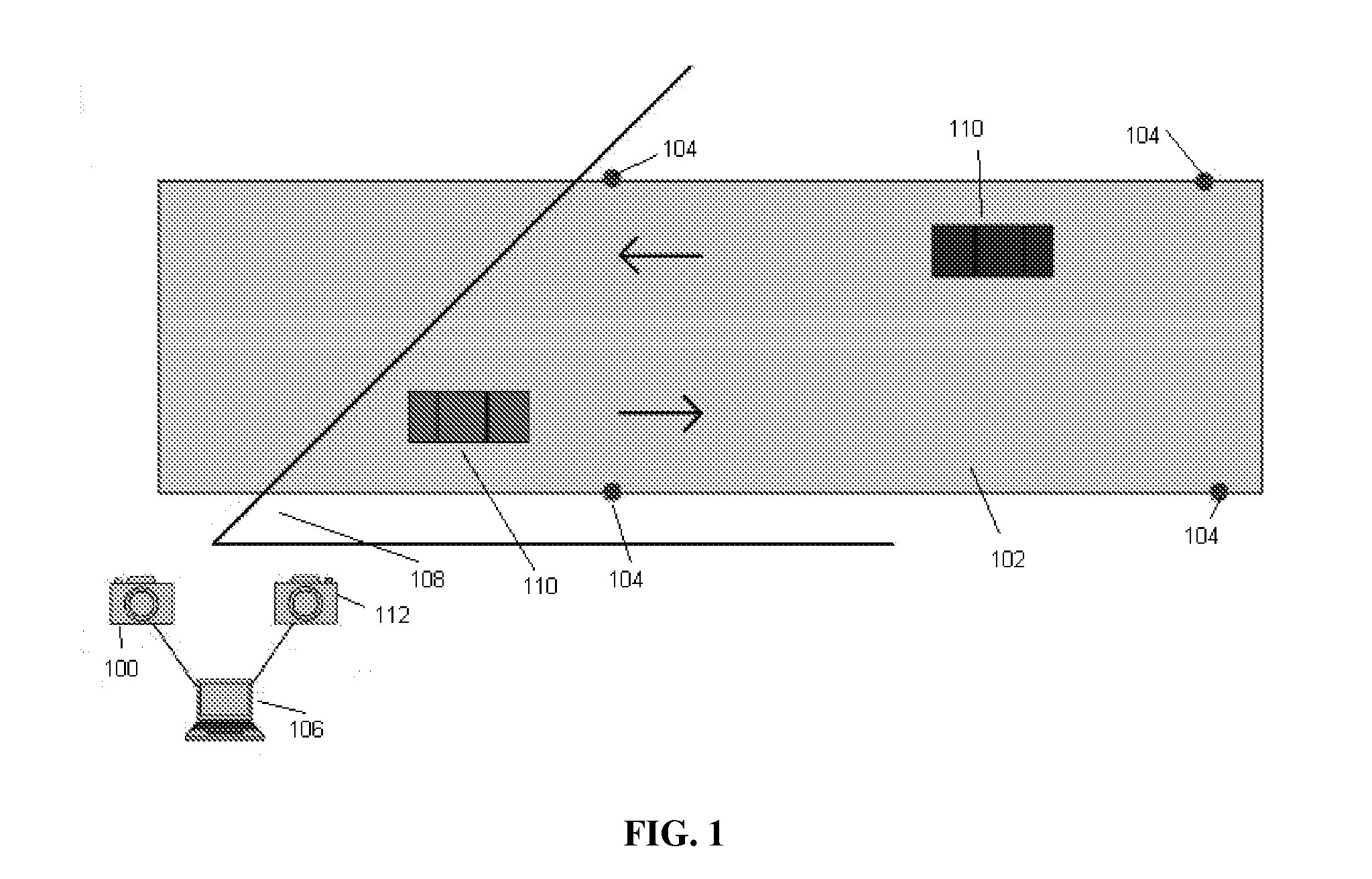
[0040]FIG. 1...


PUM


Abstract

A system and method for measuring vehicle speeds using video sensing. The system comprises a tracking camera that generates accurately time-stamped video sequences of the monitored road at high frame rates and a processing unit that analyzes the video sequences in real time to detect moving vehicles and calculate their speeds using the time-over-distance method. The system automatically detects moving vehicles in each image frame and derives vehicle positions from a projective mapping established from reference markers on the road. Time information is obtained from the date and time stamp associated with each image frame. In one example, the system also allows a user of the system to set a trigger speed, and the system automatically saves a video clip of the vehicle whose speed exceeds the trigger speed, recording the speeding vehicle passing through the monitored traffic zone defined by the reference markers.

Description

CROSS-REFERENCE TO RELATED APPLICATIONS[0001]This application claims priority under 35 U.SC. §119(e) to U.S. Provisional Patent Application No. 60 / 883,641 filed Jan. 5, 2007 entitled “NTS ViDAR™ Speed System” which is herein incorporated by reference in its entirety.BACKGROUND[0002]1. Field of Invention This invention relates generally to the measurements of vehicle speeds and, more particularly, to a system and method for measuring vehicle speeds using video sensing.[0003]2. Discussion of Related Art[0004]The traditional approach to speed limit enforcement involves police officers observing the traffic and then chasing, stopping, and issuing citations to drivers who speed. The more modern approach to speed enforcement involves the use of a speed measuring device for measuring vehicle speeds and triggering a high speed camera to take photographs of speeding vehicles. The recorded photographs are then used to identify the registered vehicle owners or actual drivers of offending vehic...

Claims


Application Information

Patent Timeline
Patent Type & Authority Applications(United States)
IPC IPC(8): H04N7/18
CPCG06T7/20G08G1/054
Inventor WANG, JIGANG
Owner AMERICAN TRAFFIC SOLUTIONS
Why Eureka
Try Eureka