Device and method for transmission of tdm signal over asynchronous network

Inactive Publication Date: 2011-11-03
NEC CORP
View PDF4 Cites 11 Cited by
  • Summary
  • Abstract
  • Description
  • Claims
  • Application Information

AI Technical Summary

Benefits of technology

[0012]According to the present invention, it is possible to increase packet transfer efficiency and a

Problems solved by technology

However, not all time slots are necessarily used in TDM circuits.
Therefore, the presence of an unused channel results in meaningless data being st

Method used


Image

  • Device and method for transmission of tdm signal over asynchronous network
  • Device and method for transmission of tdm signal over asynchronous network
  • Device and method for transmission of tdm signal over asynchronous network

Examples


Example

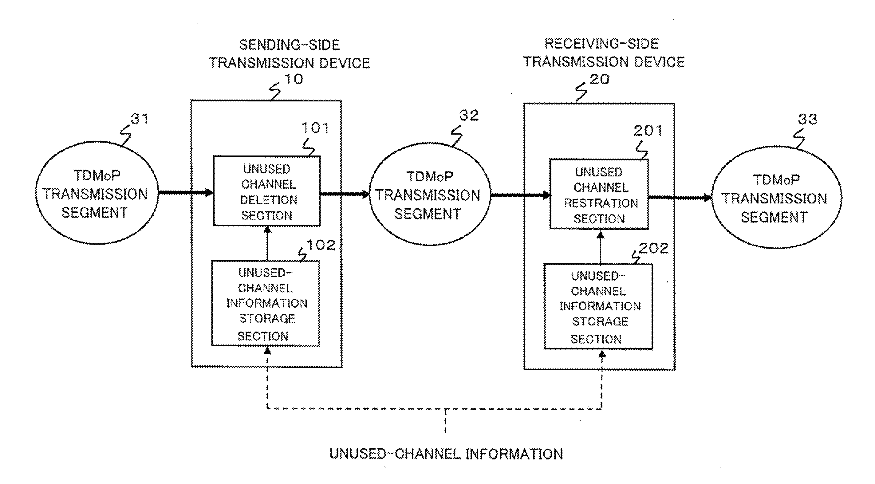
[0027]Referring to FIG. 3, a SAToP transmission system according to an exemplary embodiment of the present invention includes a sending-side transmission device 10 and a receiving-side transmission device 20 along TDMoP (TDM over Packet) transmission segments each of which is formed across a packet network by using the TDM pseudo wire emulation technology. Here, it is assumed that the sending-side transmission device 10 is located between TDMoP transmission segments 31 and 32 and that the receiving-side transmission device 20 is located between the TDMoP transmission segment 32 and a TDMoP transmission segment 33. Note that the packet network is an example of asynchronous networks and that the sending-side transmission device 10 and receiving-side transmission device 20 in FIG. 3 only show their respective functional configurations related to a transmission device according to the present exemplary embodiment.

[0028]The sending-side transmission device 10 includes an unused channel d...


PUM


Abstract

A transmission device which transmits a packet to a destination transmission device through an asynchronous network, the packet accommodating a plurality of time division multiplexing (TDM) channels, includes: an unused-channel information storage section for storing unused-channel information on an unused one of a predetermined number of TDM channels; and an unused channel deletion section for deleting an unused channel from the predetermined number of TDM channels accommodated in a received packet by referring to the unused-channel information, to generate a compressed packet to transmit to the destination transmission device.

Description

[0001]This application is based upon and claims the benefit of priority from Japanese Patent Application No. 2010-103110, filed on Apr. 28, 2010, the disclosure of which is incorporated herein in its entirety by reference.BACKGROUND OF THE INVENTION[0002]1. Field of the Invention[0003]The present invention relates to pseudo wire emulation edge to edge (hereinafter, referred to as “PWE3”) technology and, more particularly, to a device and method for transmission of a time-division-multiplexed signal over a asynchronous network such as an Ethernet™ (hereinafter, simply referred to as “Ether”) and a packet-switched network.[0004]2. Description of the Related Art[0005]Various circuit emulation technologies are proposed to transport time division multiplexing (TDM) circuits over an asynchronous network such as a packet network (for example, see Japanese Patent Application Unexamined Publication No. 2008-135819). Particularly in Request for Comments: 4553 “Structure-Agnostic Time Division...

Claims


Application Information

Patent Timeline
IPC IPC(8): H04L12/43H04L47/43H04J3/00
CPCH04L12/43
Inventor KOBATAKE, YOSHIHARU
Owner NEC CORP
Why Eureka
Try Eureka