

Coherent augmented optical add-drop multiplexer
- Summary
- Abstract
- Description
- Claims
- Application Information
AI Technical Summary
Problems solved by technology
Method used
Image

Examples
Embodiment Construction
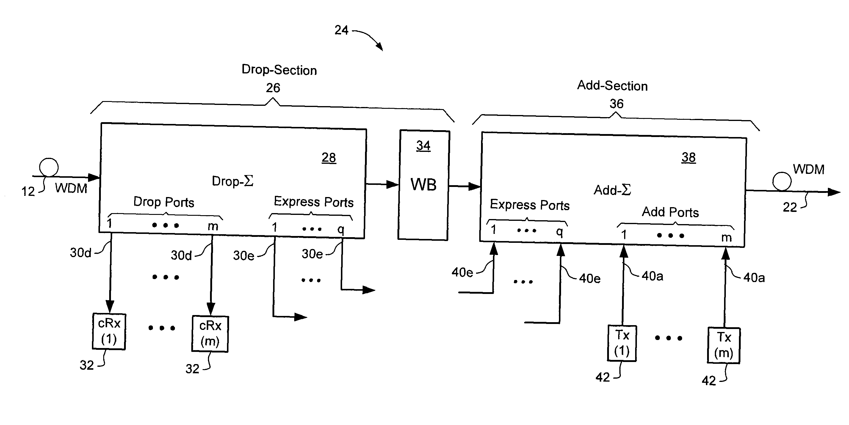
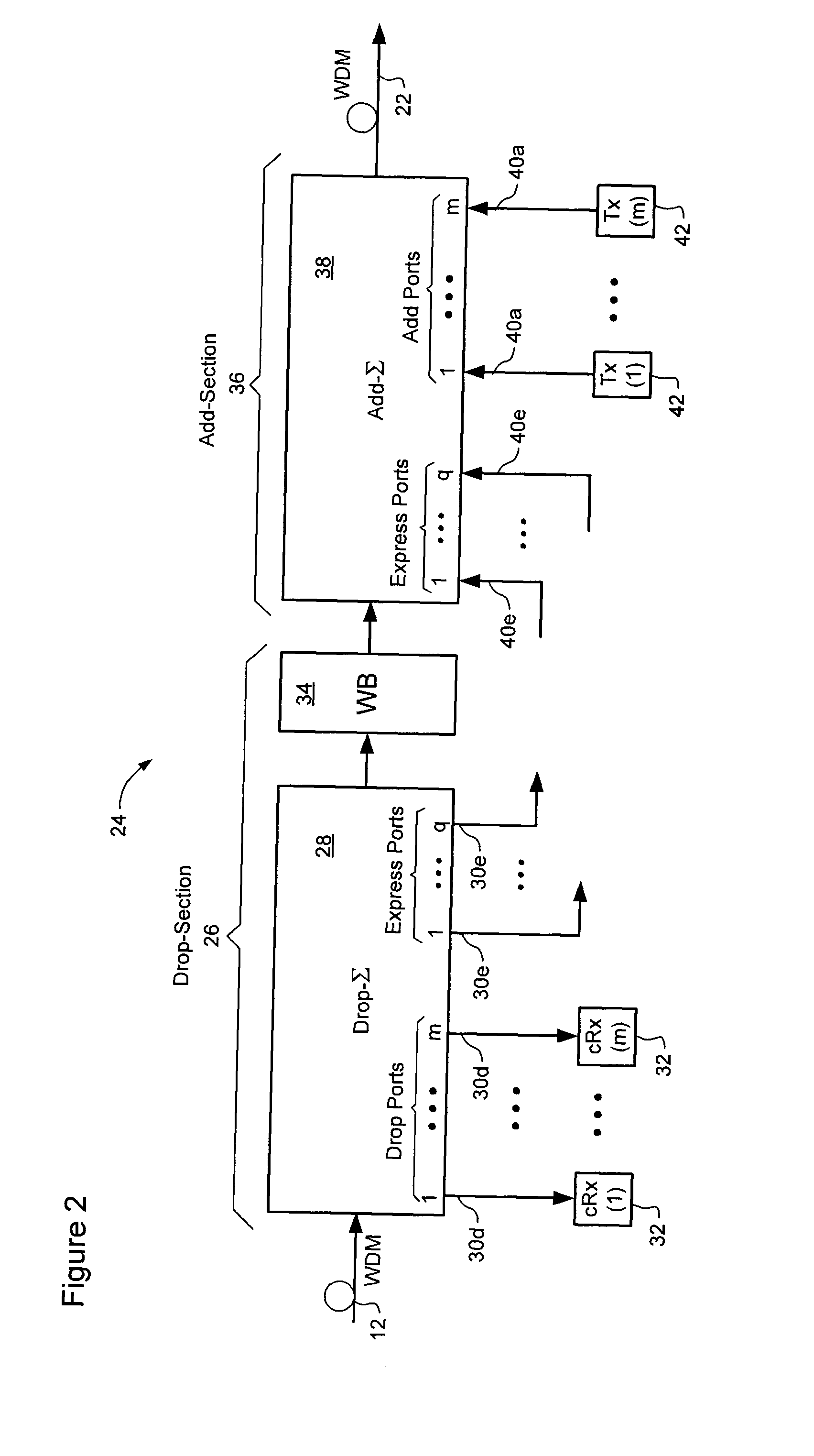
[0022]The present invention provides methods and systems in which a moderate port count Wavelength Selective Switch (WSS) and a plurality of moderate Common Mode Rejection Ratio (CMRR) coherent receivers are used in combination to achieve a high drop-ratio Optical Add-Drop Multiplexer (OADM). Embodiments of the present invention are described below, by way of example only, with reference to FIG. 3.
[0023]FIG. 3a is a block diagram schematically illustrating a drop section 44 of a representative coherent augmented OADM in accordance with an aspect of the present invention. In the embodiment of FIG. 3, an n-channel Wavelength Division Multiplexed (WDM) signal is input to a drop section WSS 46 having a set of p ports 48, which are allocated between q (where q>0) express ports 48e and m (where m=p-q) drop ports 48d.
[0024]As is known in the art, a WSS is capable of routing any given channel from the input WDM signal to any one of the ports 48. In the embodiment of FIG. 3a, this functiona...
PUM
 Abstract
Description
Claims
Application Information