
Automated Immunoassay Apparatus

an immunoassay and automatic technology, applied in the field of automatic immunoassay equipment and enzyme linked immunosorbent assay system, can solve the problems of manual operation system, comparatively expensive equipment, and inability to generally match other manufacturers' equipment, and achieve fast results

Inactive Publication Date: 2011-11-03
DYNEX TECH
View PDF2 Cites 1 Cited by
  • Summary
  • Abstract
  • Description
  • Claims
  • Application Information

AI Technical Summary

Benefits of technology

The present invention provides an automated immunoassay apparatus that can read microtitre plates quickly and accurately. The apparatus has a first mechanism for moving a first microtitre plate and a second mechanism for moving a second microtitre plate. The first mechanism can move the first microtitre plate in a forward and backward motion along a first axis, while the second mechanism can move the second microtitre plate in a forward and backward motion along a second axis. The apparatus also has a reading device that can read both microtitre plates simultaneously. The apparatus can dispense samples and aspirate samples from the microtitre plates. The second microtitre plate can be positioned at different heights along its length, and the apparatus can also have a contoured track to move the second microtitre plate up and down in height. The technical effects of the invention include improved automation and efficiency in immunoassay testing, reduced human error, and improved accuracy and reliability of the testing results.

Problems solved by technology

Latex consumable tests are used, for example, in home pregnancy testing kits and are fast, reasonably accurate but are comparatively expensive.
Such equipment is comparatively expensive and is not generally compatible with other manufacturers' equipment.
Radioactive markers are less preferred due to environmental and safety concerns regarding their handling, storage and disposal.
However, as can be appreciated, manually operated systems suffered from a number of problems including variable results with a limited dynamic / range.
The technician was also unduly exposed to potentially biohazardous material.
Failure to wash the microplate after sample incubation would de-sensitise the process as the fluid content of the sample needs to be removed for subsequent reagent additions to take place.
This results in a relatively complex, large and hence correspondingly expensive system.

Method used


Image

  • Automated Immunoassay Apparatus
  • Automated Immunoassay Apparatus
  • Automated Immunoassay Apparatus

Examples


Embodiment Construction

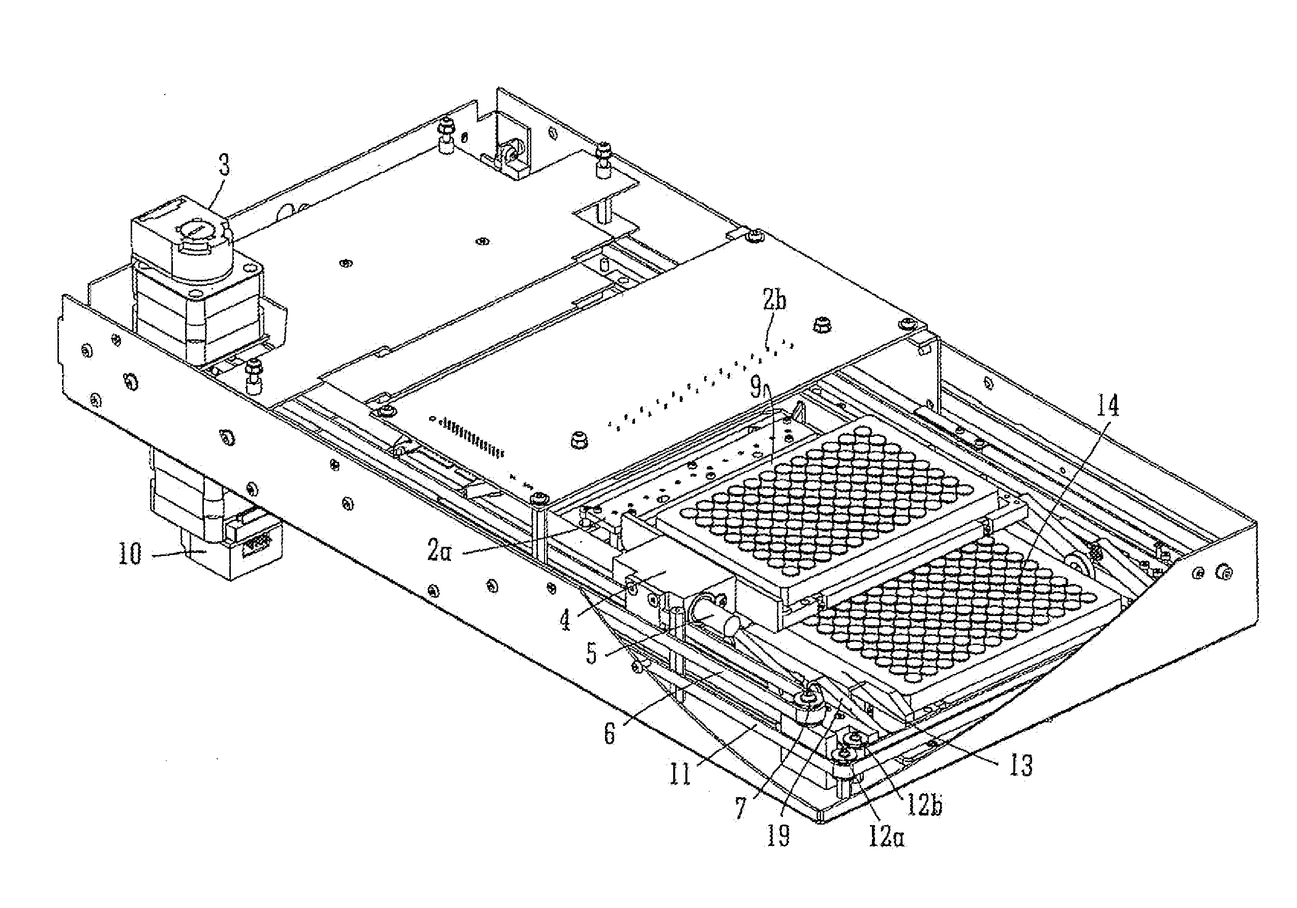
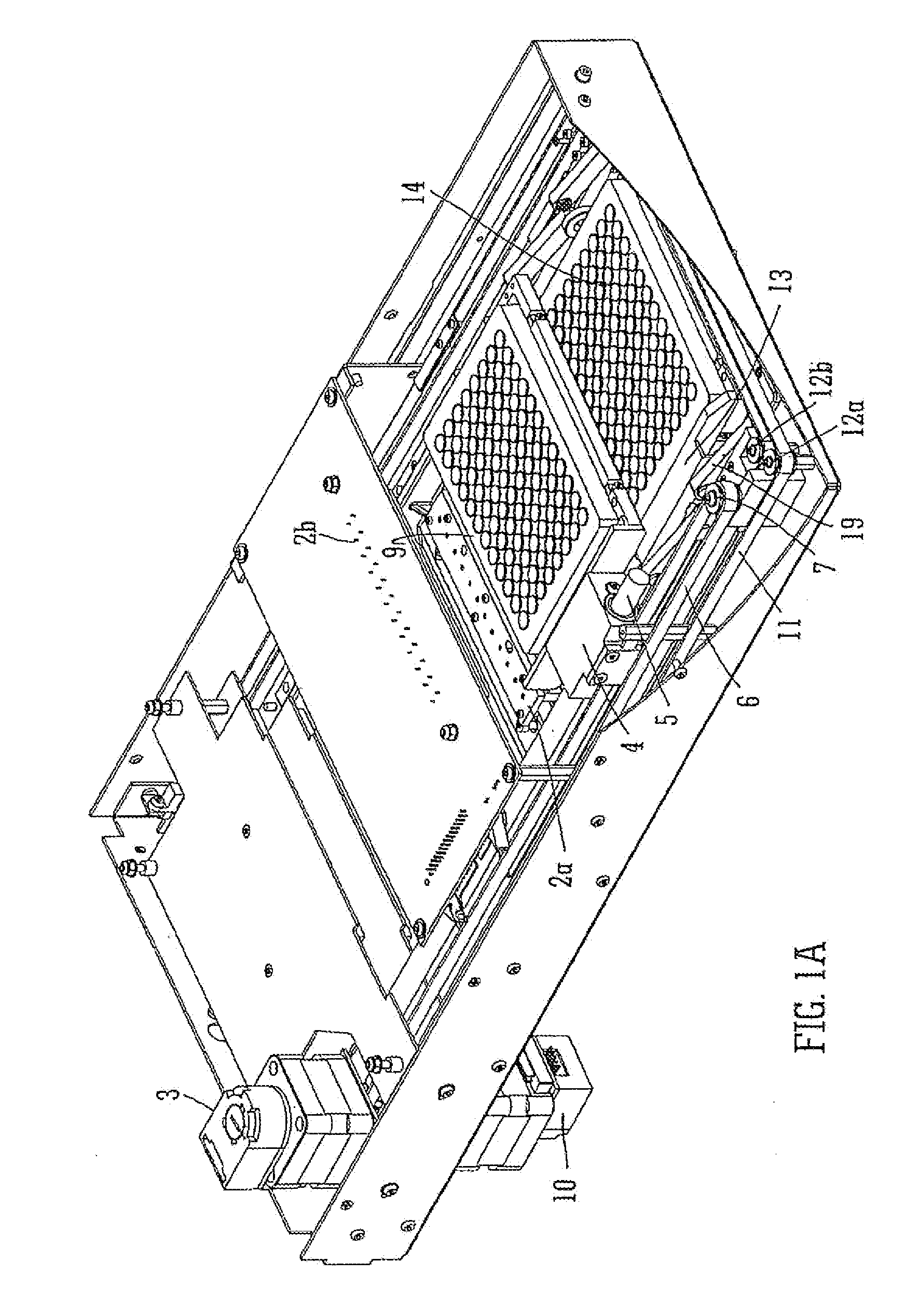
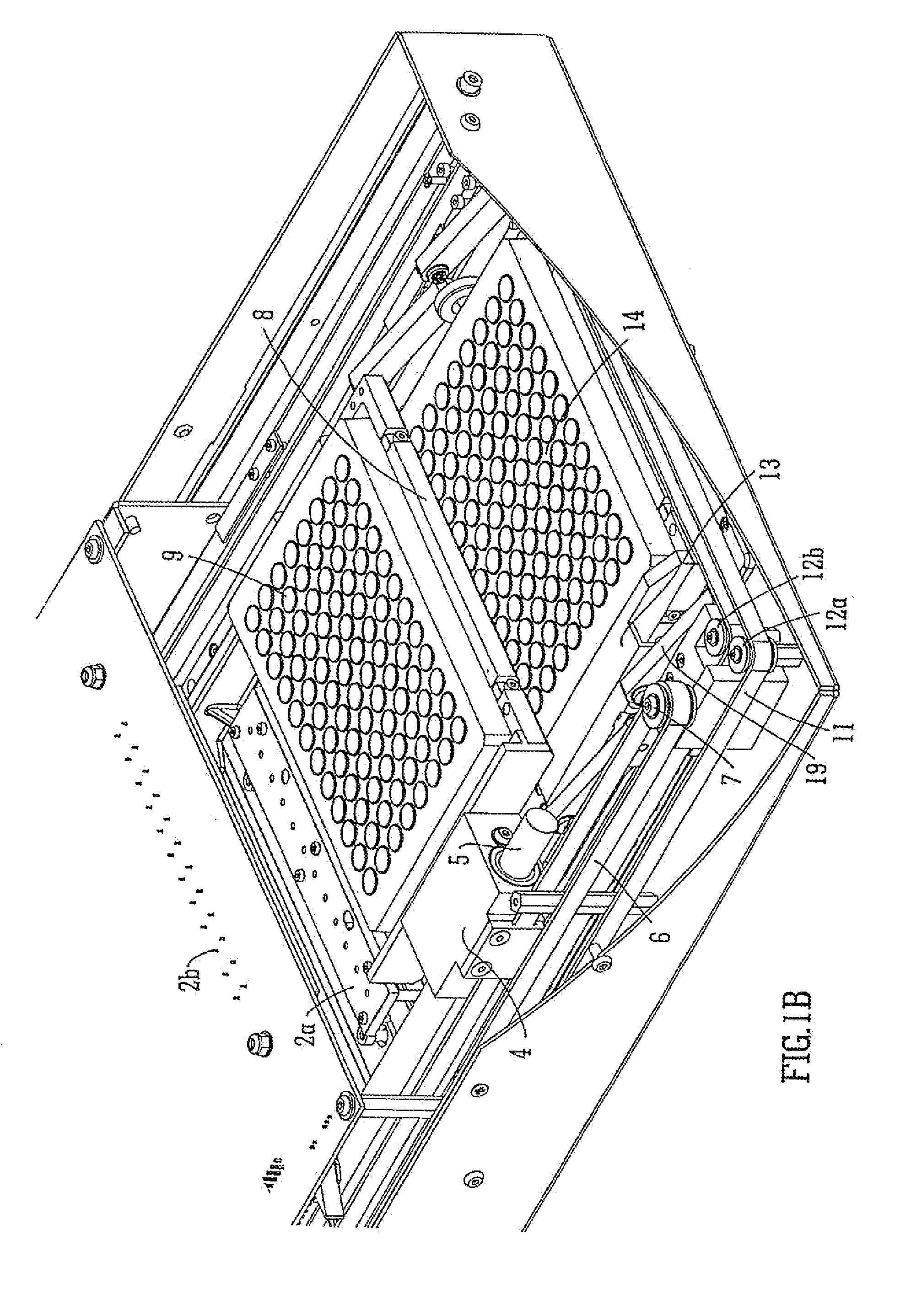
[0138]A first main preferred embodiment of the present invention relating to an immunoassay apparatus for reading two microtitre plates using a single reader device will now be described with reference to FIGS. 1-13B. FIG. 1 shows an automated immunoassay apparatus 1 according to a preferred embodiment which preferably comprises a single optical reading device 2a, 2b for reading two microtitre plates 9, 14. The microtitre plates 9, 14 are preferably loaded at the front of the apparatus 1 and are preferably translated over or through the optical reading device 2a, 2b in order to be read by the Optical, reading device 2a, 2b. The. optical reading device 2a, 2b preferably comprises a strip or line of twelve photo-emitters or photodiodes 2a as shown in FIG. 1A. The light emitters are preferably positioned below a microtitre plate and the microtitre plate preferably passes above or over the light-emitters, A strip or line of photodiodes 2b is preferably arranged or positioned above the m...


PUM

PropertyMeasurementUnit
volumeaaaaaaaaaa
heightaaaaaaaaaa
heightaaaaaaaaaa

Abstract

An automated immunoassay apparatus is disclosed comprising a single optical reading device for reading two microtitre plates. A first microtitre plate is loaded into an upper plate holder which is linearly translated at a fixed height. A second microtitre plate is loaded into a lower plate holder. The lower plate, holder runs along a contoured track which varies the vertical height of the second microtitre plate.

Description

CROSS-REFERENCE TO RELATED APPLICATIONS[0001]This application represents a divisional application of U.S. application Ser. No. 12 / 084,879, filed May 12, 2008, pending, which represents a National Stage application of PCT / GB2006 / 0.04213 filed Nov. 10, 2006 entitled “Automated Immunoassay Apparatus”, pending.BACKGROUND OF THE INVENTION[0002]The present invention relates to an automated immunoassay apparatus, an Enzyme Linked Immunosorbent Assay system, a method of reading microtitre plates, a deep well or dilution strip and a dilution strip holder.[0003]The preferred embodiment relates to automated immunoassay apparatus for carrying out diagnostic testing and in particular to apparatus for carrying out Enzyme Linked Immunosorbent Assay (“ELISA”) procedures.[0004]A number of different testing techniques for biological products are known and these include latex consumable jests and Polymerase Chain Reaction (“PCR”) tests.[0005]Latex consumable tests are used, for example, in home pregna...

Claims


Application Information

Patent Timeline
Patent Type & Authority Applications(United States)
IPC IPC(8): B01L3/00G01N35/02G01N35/04
CPCG01N35/028G01N35/04G01N2035/0424Y10T436/11Y10T436/114165Y10T436/113332G01N2035/0425
Inventor BUNCE, ADRIANFUSELLIER, ANDREW
Owner DYNEX TECH
Learn More