Electronic control apparatus

a control apparatus and electronic technology, applied in electrical control, program control, instruments, etc., can solve the problems of insufficient responsiveness to serial signals, increased number of input terminals of microprocessors, and inability to suppress outputs of concurrently utilized microprocessors, etc., to reduce the number of input signal lines and output signal lines of microprocessors.

Active Publication Date: 2011-11-10
MITSUBISHI ELECTRIC CORP
View PDF2 Cites 13 Cited by
  • Summary
  • Abstract
  • Description
  • Claims
  • Application Information

AI Technical Summary

Benefits of technology

[0015]The objective of the present invention is to provide an intelligent power module, to be applied to a multi-purpose electronic control apparatus, in which an intelligent power module including a plurality

Problems solved by technology

In the “intelligent power module” disclosed in Patent Document 1, the respective cause-discriminated abnormality occurrence statuses of the plurality of switching devices can be read through a serial signal and hence the number of input signals of, for example, a microprocessor that is concurrently utilized can be suppressed; however, because it is required to supply a control signal to each opening/closing device, there is posed a drawback that the number of the outputs of the concurrently utilized microprocessor cannot be suppressed, even in the case of a simple application where part or all of the opening/closing devices perform opening/closing operation at low frequency.
In the “intelligent power module” disclosed in Patent Document 2, temperature information on the opening/closing device can be read by, for example, a concurrently utilized microprocessor; however, there is posed a drawback that, when an A/D converter is provided in the intelligent power module, the number of input terminals of the microprocessor is increased due to reading of the digital value of the temperature information.
Furthermore, in the “total control apparatus for an automobile” disclosed in Patent Document 3, even though the number of the wire leads for opening/closing signals can be reduced in an application where a great number of opening/closing devices are simply opening/closing-controlled; however, in the case of an opening/closing device that needs to perform high-speed operation such as

Method used


Image

  • Electronic control apparatus
  • Electronic control apparatus
  • Electronic control apparatus

Examples


embodiment 1

(1) Detailed Description of Configuration

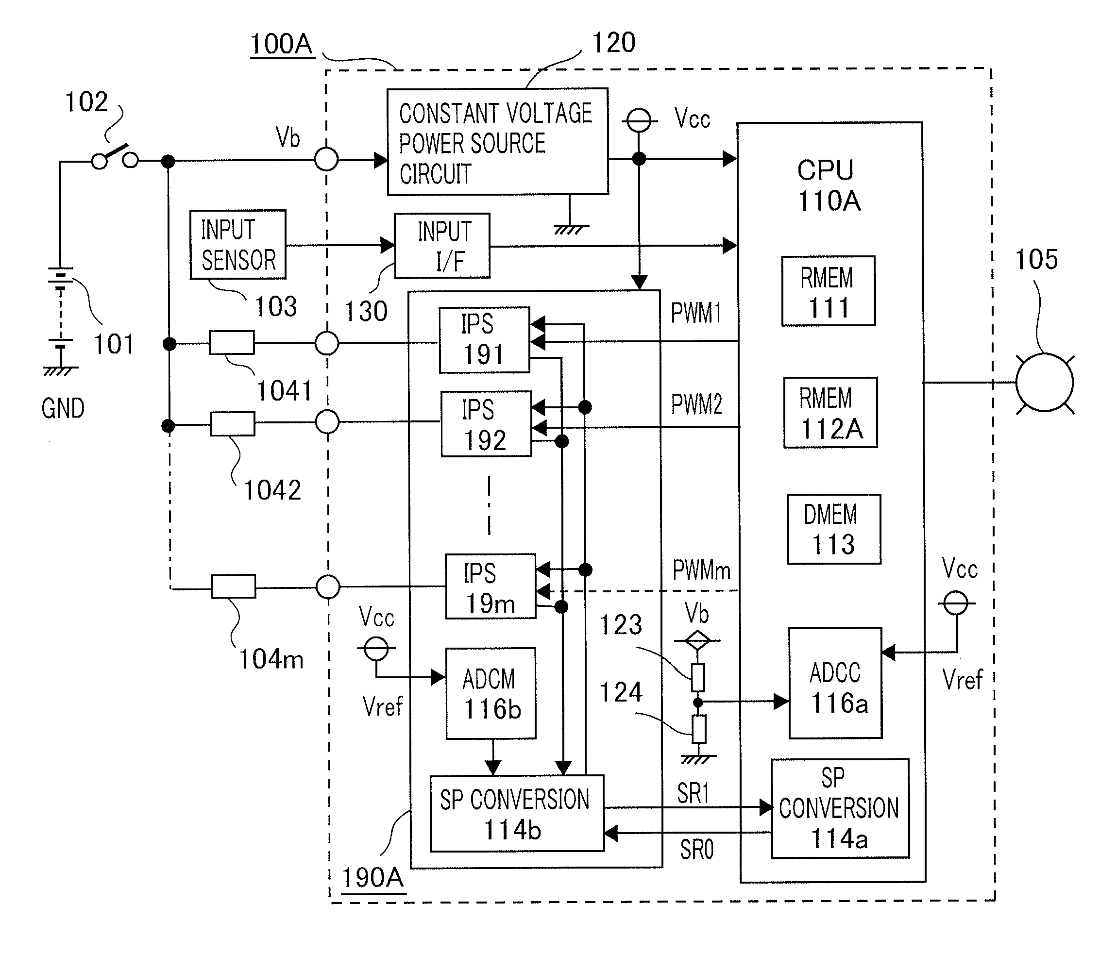
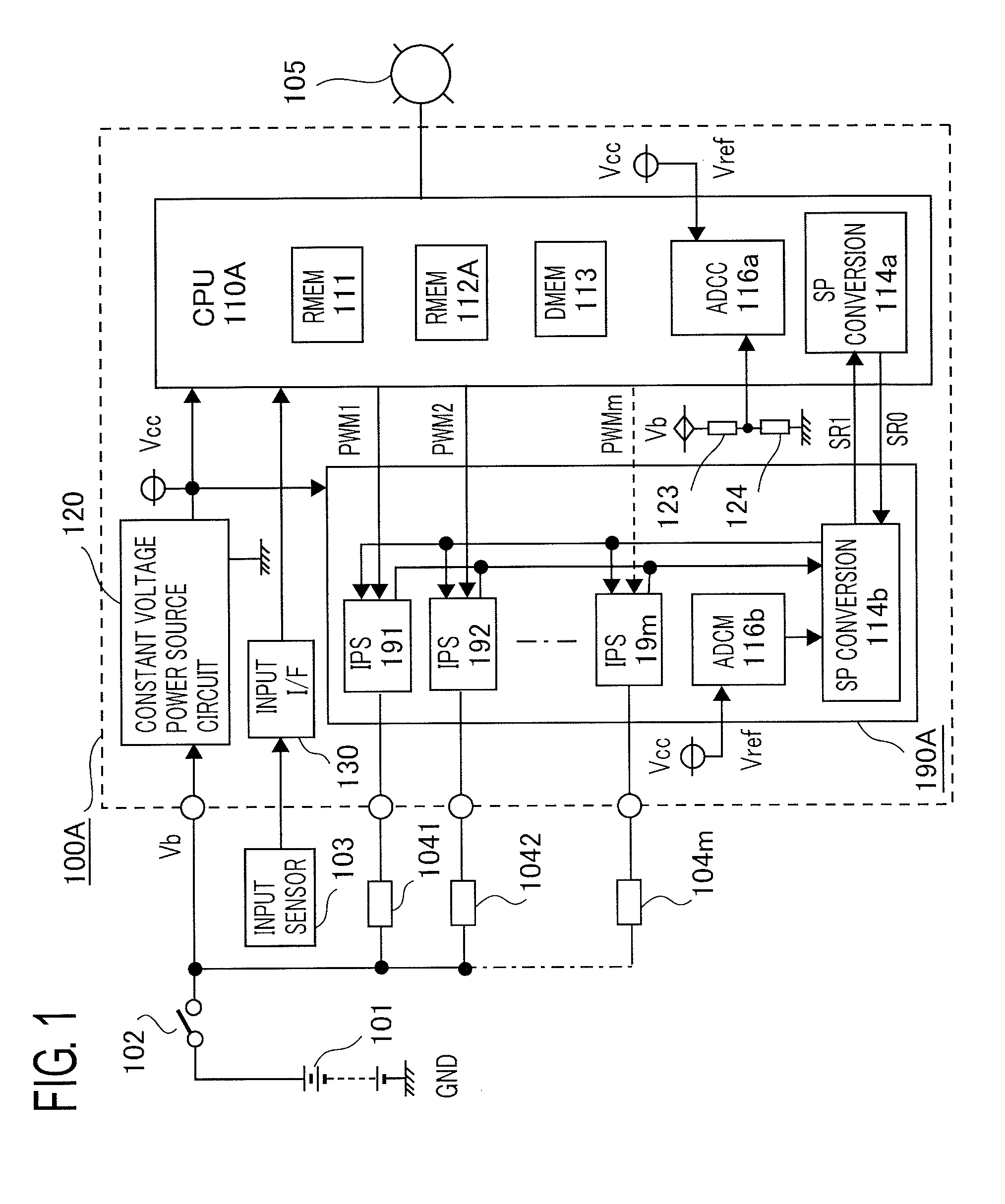
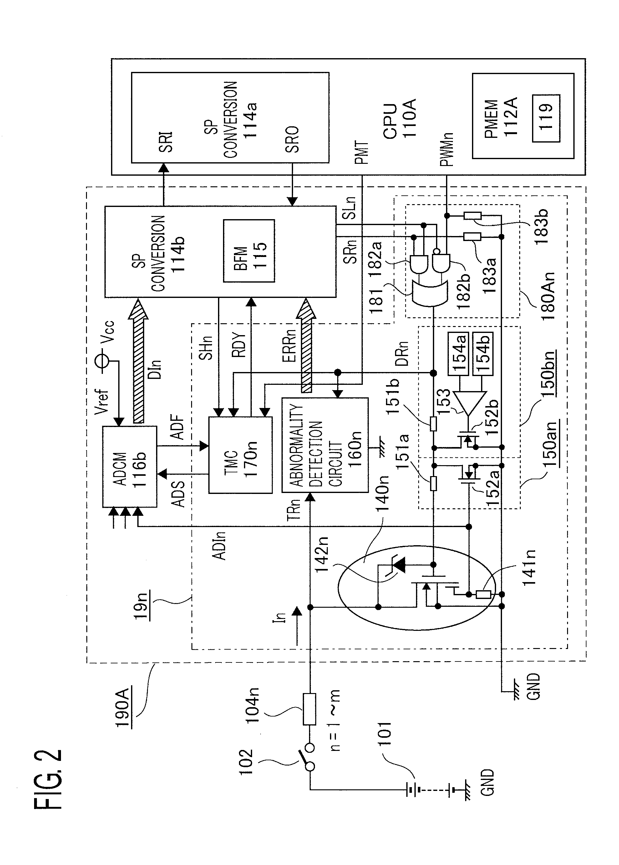
[0035]At first, there will be explained the configuration of an electronic control apparatus according to Embodiment 1 of the present invention. FIG. 1 is a block diagram illustrating the overall configuration of an electronic control apparatus according to Embodiment 1 of the present invention; FIG. 2 is a block diagram illustrating the detail of an intelligent power module in an electronic control apparatus according to Embodiment 1 of the present invention. In FIG. 1, an electronic control apparatus 100A is configured mainly with a microprocessor 110A, an intelligent power module (referred to as an IPM, hereinafter) 190A, a constant voltage power source circuit 120, and an input interface circuit 130.

[0036]The electronic control apparatus 100A receives electric power from an external power source 101, which is, for example, a vehicle battery, by way of a power switch 102, and supplies a power-source voltage Vb to the constant voltage power...

embodiment 2

(1) Detailed Description of Configuration

[0148]Next, there will be explained an electronic control apparatus according to Embodiment 2 of the present invention. FIG. 7 is a block diagram illustrating the overall configuration of an electronic control apparatus according to Embodiment 2 of the present invention. Different points between FIG. 7 and FIG. 1 will mainly be explained. In each of the drawings, the same reference characters denote the same or similar portions. In FIG. 7, an electronic control apparatus 100B is configured mainly with a microprocessor 110B, an IPM 190B, the constant voltage power source circuit 120, and the input interface circuit 130.

[0149]The microprocessor 110B includes the volatile RAM memory 111, a nonvolatile program memory 112B, the nonvolatile data memory 113, the serial-parallel converter 114a, and the first multi-channel A / D converter 116a. The IPM 190B is provided with, for example, 14 IPSs 191, 192, - - - , 19m (m=14), and performs serial communic...

embodiment 3

(1) Detailed Description of Configuration and Operation

[0221]Next, there will be explained an electronic control apparatus according to Embodiment 3 of the present invention. FIG. 13 is a block diagram illustrating the overall configuration of an electronic control apparatus according to Embodiment 3 of the present invention. Different points between FIG. 13 and FIG. 1 will mainly be explained. In each of the drawings, the same reference characters denote the same or similar portions. In FIG. 13, an electronic control apparatus 100C is configured mainly with a microprocessor 110C, an IPM 190C, the constant voltage power source circuit 120, and the input interface circuit 130.

[0222]The microprocessor 110C includes the volatile RAM memory 111, a nonvolatile program memory 112C, the nonvolatile data memory 113, the serial-parallel converter 114a, and the first multi-channel A / D converter 116a. The IPM 190C is provided with, for example, 14 IPSs 191, 192, - - - , 19m (m=14), and perform...


PUM


Abstract

An electronic control apparatus 100A is configured in such a way that a CPU 110A reads the conduction current of an opening/closing device 140n in an IPM 190A, by way of serial-parallel converters 114a and 114b and a second multi-channel A/D converter 116b; the opening/closing device 140n is opening/closing-controlled through a serial control signal SRn or a parallel control signal PWMn; and a reading timing control circuit 170n adjusts the reading timing in such a way that, regardless of the kind of the control signal, reading is performed during the period in which the opening/closing device 140n is driven to be closed. As a result, the serial-parallel converter can reduce the number of wiring leads between the IPM and the microprocessor, and the digital conversion value is accurately read, by adjusting the error between the serial-signal timing and the parallel-signal timing.

Description

BACKGROUND OF THE INVENTION[0001]1. Field of the Invention[0002]The present invention relates to an electronic control apparatus mounted in a vehicle or the like, and particularly to improvement of a signal communication circuit situated between an intelligent power module including a plurality of opening / closing devices, a multi-channel A / D converter, and a serial-parallel converter and a microprocessor that collaborates with the intelligent power module.[0003]2. Description of the Related Art[0004]With regard to an electronic control apparatus mounted in a vehicle or the like, there is publicly known an electronic control apparatus in which a plurality of opening / closing devices that are supplied with electric power from an external power source and perform energization drive of a plurality of electric loads, respective excess current cutoff circuits and overheat shutoff circuits for the opening / closing devices, and an abnormality detection circuit are integrated and are connected...

Claims


Application Information

Patent Timeline
IPC IPC(8): G06F1/28
CPCG05B9/02F02D41/28
Inventor ZUSHI, YUJISUZUKI, SHINSUKEISHII, AKIHIRO
Owner MITSUBISHI ELECTRIC CORP
Why Eureka
Try Eureka