Load Balancer and Load Balancing System

Inactive Publication Date: 2011-11-10
HITACHI LTD
View PDF2 Cites 107 Cited by
  • Summary
  • Abstract
  • Description
  • Claims
  • Application Information

AI Technical Summary

Benefits of technology

[0017]The load balancer can distribute, in consideration of influence from the packet loss taking place

Problems solved by technology

When the load is distributed to a server in the least connection algorithm, the load balancer cannot know the current state of the server.
Hence, it is likely to send requests to the server, the requests exceeding the processing capacity of the server.
When the CPU resource sharing is set to a plurality of virtual server groups, it is l

Method used


Image

  • Load Balancer and Load Balancing System
  • Load Balancer and Load Balancing System
  • Load Balancer and Load Balancing System

Examples


first embodiment

1. First Embodiment

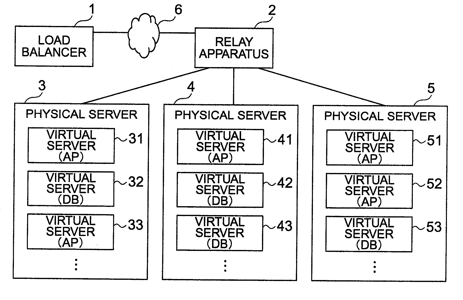
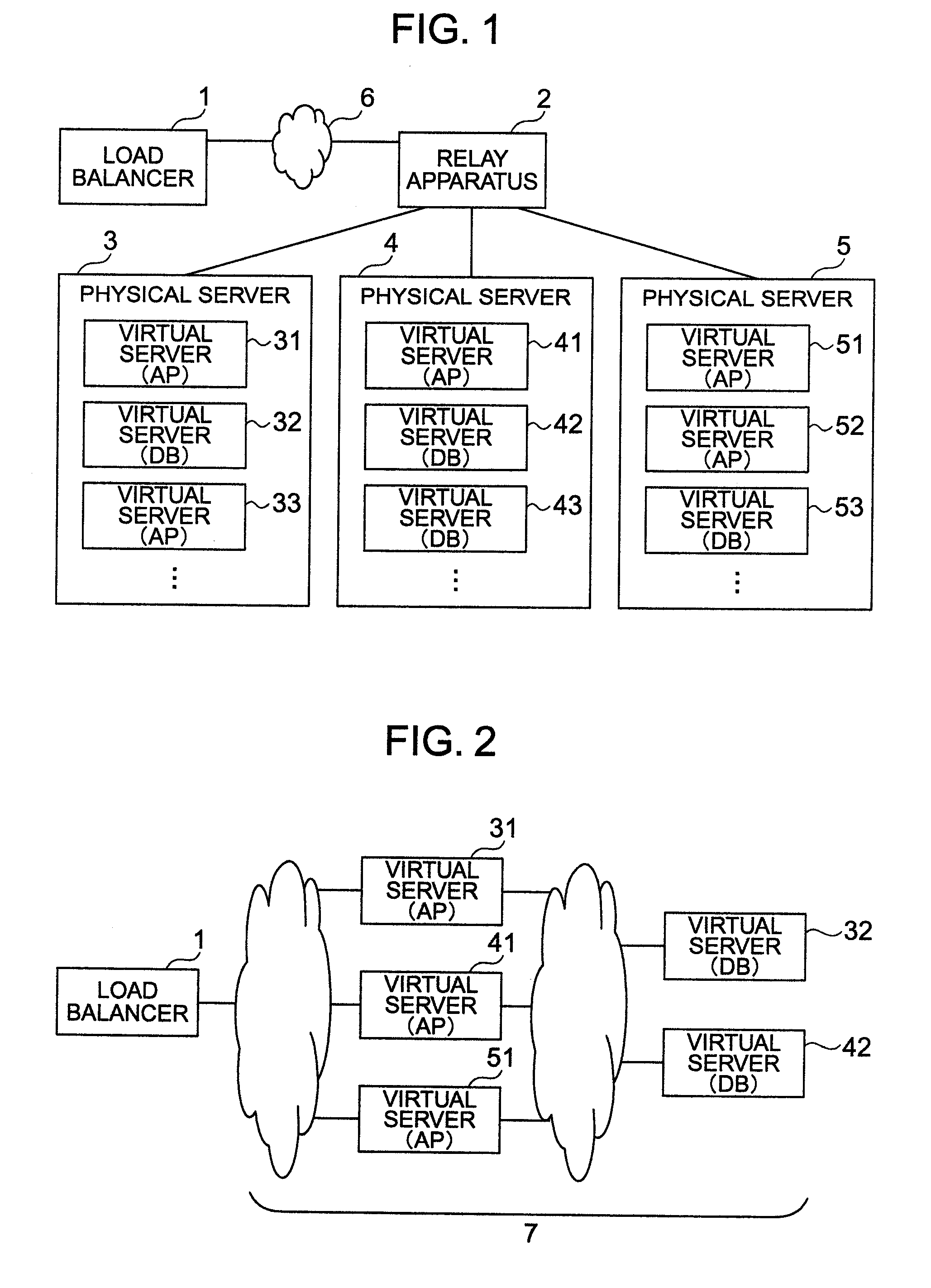
[0036]FIG. 1 shows a configuration of a request processing system in a first embodiment according to the present invention. The request processing system of the first embodiment includes a load balancer 1, a relay apparatus 2, physical servers 3 to 5, virtual servers 31 to 33 of the physical server 3, virtual servers 41 to 43 of the physical server 4, virtual servers 51 to 53 of the physical server 5, and a network 6 to connect the load balancer 1 to the relay apparatus 2.

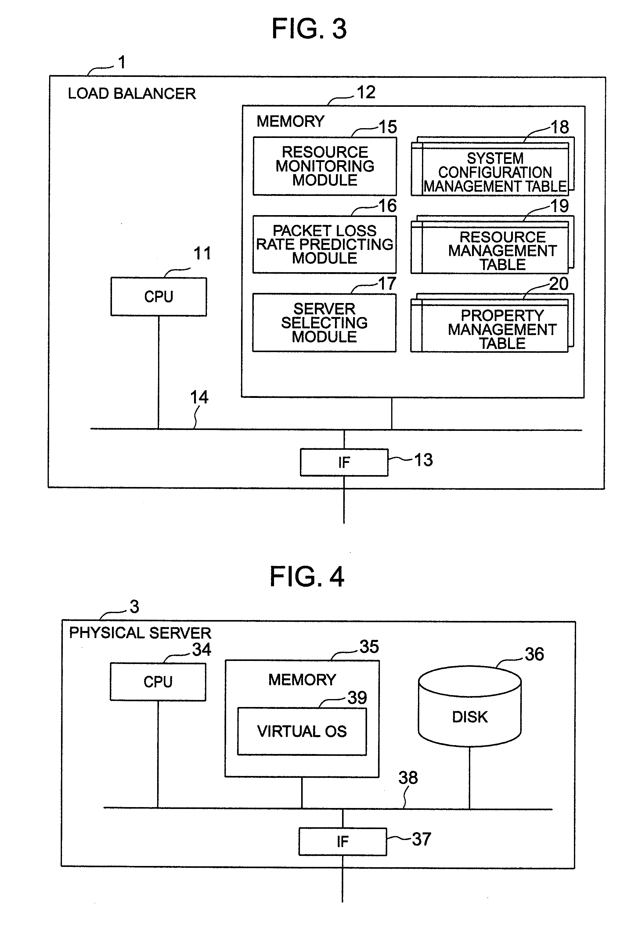
[0037]The load balancer 1 is an apparatus to select an appropriate virtual server from the virtual servers of the web system and to transfer a request to the virtual server. Among the relay apparatuses of the network 6 to connect the load balancer 1 to the physical servers, the relay apparatus 2 directly connects to the physical servers 3 to 5. Due to the direct connections, it is possible to assume that Internet Protocol (IP) packets and frames sent from the relay apparatus 2 to the physical ser...

second embodiment

2. Second Embodiment

[0082]In the first embodiment, to obtain an index in association with the reduction in processing capacity due to the packet loss for each virtual server as the candidate of the request transfer destination, the value of the available CPU resource amount obtained based on the difference between the CPU assignment rate and the actual CPU utilization is multiplied by a reciprocal of the packet loss rate. In the second embodiment, for each virtual server as the candidate of the request transfer destination, data items of the request processing count corresponding to a combination of a plurality of values respectively of the CPU assignment rate and the packet loss rate are beforehand stored in a table such that an index of each virtual server is obtained from the table. This also leads to request transfer destination selection substantially equal to that of the first embodiment. The request processing system of the second embodiment is similar in the physical configu...

third embodiment

3. Third Embodiment

[0089]In the third embodiment, at selection of a virtual server as the request transfer destination, the packet loss rate of the virtual server is not obtained. In place thereof, the CPU resource of the virtual server is directly converted into the number of requests processible by the virtual server, to thereby select one of the virtual servers as the request transfer destination. The request processing system of the third embodiment is similar in the physical configuration and the main logical configuration to that of the first embodiment.

[0090]In the virtual switch 40, the packet loss takes place in association with the CPU utilization of the overall physical server and the input packet rate of the physical server. Therefore, in place of the table keeping therein data items of the request processing numbers for various values of the CPU assignment rate of the virtual server and the packet loss rate of the virtual switch, a table keeping therein data items of th...


PUM


Abstract

In a system including a load balancer to select a virtual server to which a request is to be transferred, the load balancer includes a function to monitor resource use states of physical and virtual servers and a function to predict a packet loss occurring in a virtual switch. The request count of requests processible by each virtual server is calculated based on the resource amount available for the virtual server and a packet loss rate of the virtual switch, to thereby select a virtual server capable of processing a larger number of requests.

Description

INCORPORATION BY REFERENCE[0001]The present application claims priority from Japanese application JP2010-106087 filed on May 6, 2010, the content of which is hereby incorporated by reference into this application.BACKGROUND OF THE INVENTION[0002]The present invention relates to a load balancer and a load balancing method for use with a request processing system in a virtual environment for distributing requests issued to the system to a plurality of virtual servers.[0003]Due to advance and development in performance of hardware, attention has been drawn to a server virtualizing technique to logically divide one physical server into a plurality of virtual servers. According to this technique, resources available for virtual servers may be freely selected for allocation thereof to the virtual servers from the resources of the physical server such as a Central Processing Unit (CPU), a memory, a hard disk, and a network. Also, for a resource thus allocated, a plurality of virtual server...

Claims


Application Information

Patent Timeline
IPC IPC(8): G06F9/46
CPCG06F9/505H04L67/101H04L67/1029H04L67/1008
Inventor NAKAYAMA, MARIKOKUMAGAI, ATSUYASUGAUCHI, KIMINORITOUMURA, KUNIHIKO
Owner HITACHI LTD
Why Eureka
Try Eureka