Multi-Function Medical Room System

a multi-functional, medical room technology, applied in special buildings, schools, roofing, etc., can solve problems such as difficulty and risk, no guarantee of multiple appointments, and residents being injured

Inactive Publication Date: 2011-11-17
BOEKELOO STUART W
View PDF16 Cites 10 Cited by
  • Summary
  • Abstract
  • Description
  • Claims
  • Application Information

AI Technical Summary

Problems solved by technology

Often, the preparation and transport of elderly patients, especially for less invasive, or non-invasive procedures, can pose some difficulty and risk.
While, in some instances, it may be possible to transport multiple residents at the same time, there is no guarantee that multiple appointments can be made which are convenient, and it is often the case that residents are individually transported.
Additionally, and especially in the winter months, residents can be injured through slip and fall accidents, or can succumb to illnesses due to the exposure to the outside conditions.
Problematically, however, there is often not a proper facility in which to treat a patient in a nursing home.
Furthermore, nursing homes have been reluctant to provide multiple treatment rooms for different medical practitioners due to, among other things, space considerations and equipment cost considerations.
While such individuals are typically do not have the mobility concerns, the shear cost of transporting a single individual for treatment becomes cost prohibitive.
Problematically, again, the drawback has been the lack of a properly configured facility in which multiple medical practitioners can perform necessary procedures.

Method used


Image

  • Multi-Function Medical Room System
  • Multi-Function Medical Room System
  • Multi-Function Medical Room System

Examples


Embodiment Construction

While this invention is susceptible of embodiment in many different forms, there is shown in the drawings and described herein in detail a specific embodiment with the understanding that the present disclosure is to be considered as an exemplification and is not intended to be limited to the embodiment illustrated.

It will be understood that like or analogous elements and / or components, referred to herein, may be identified throughout the drawings by like reference characters. In addition, it will be understood that the drawings are merely schematic representations of the invention, and some of the components may have been distorted from actual scale for purposes of pictorial clarity.

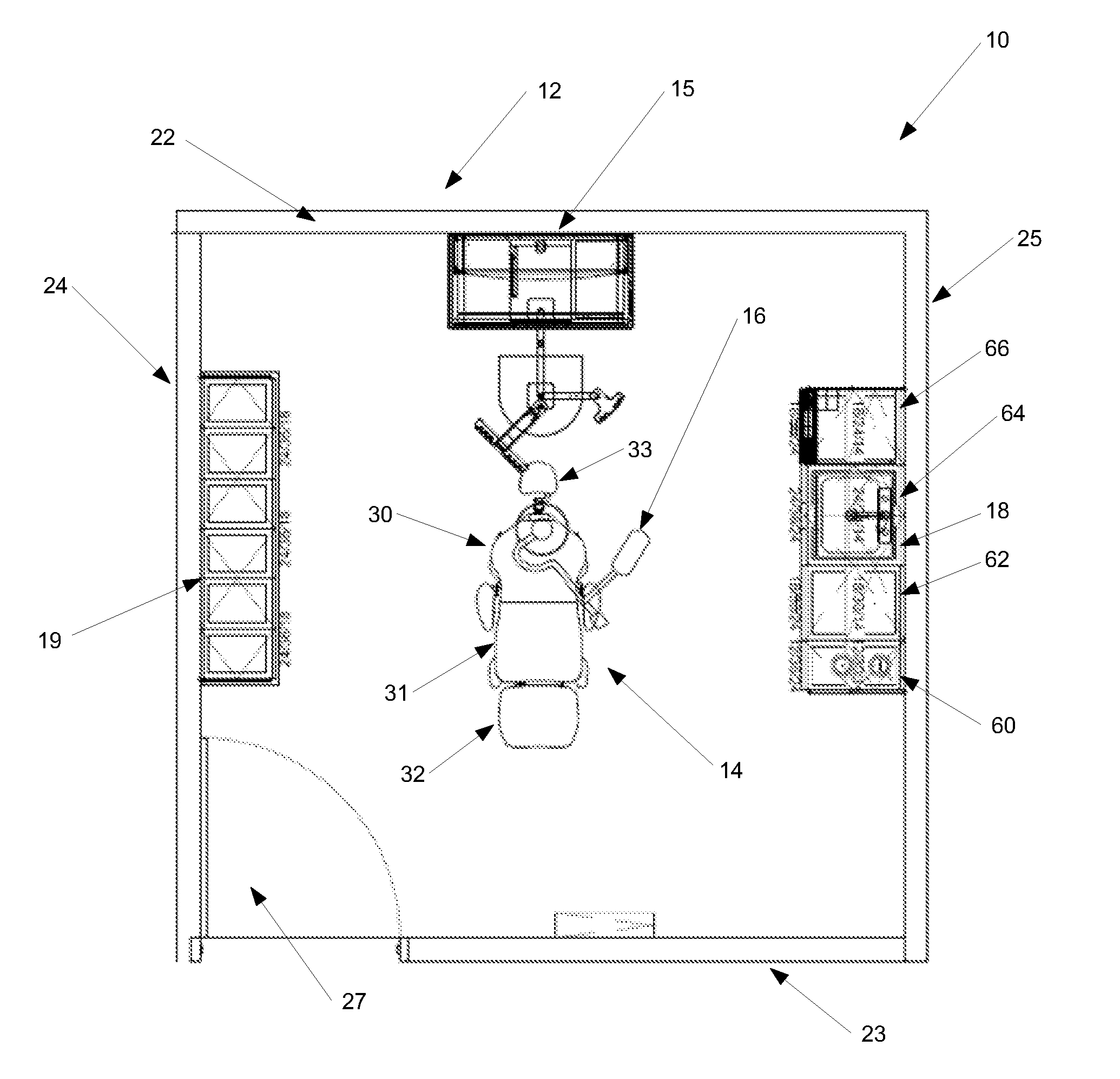
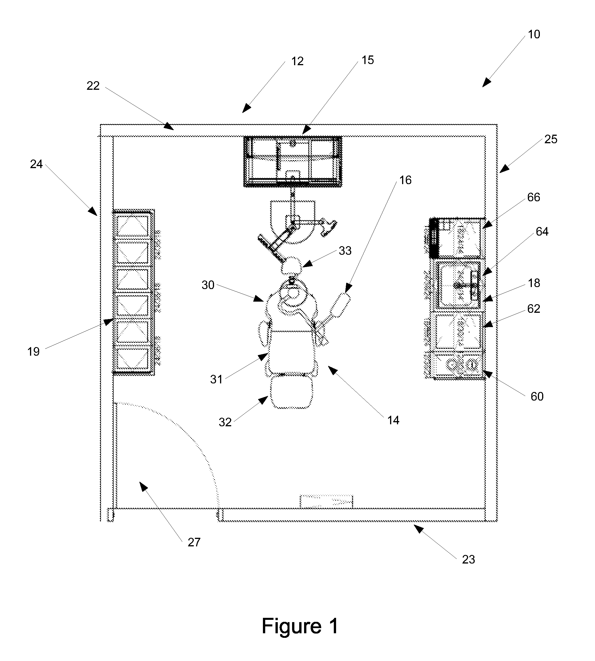
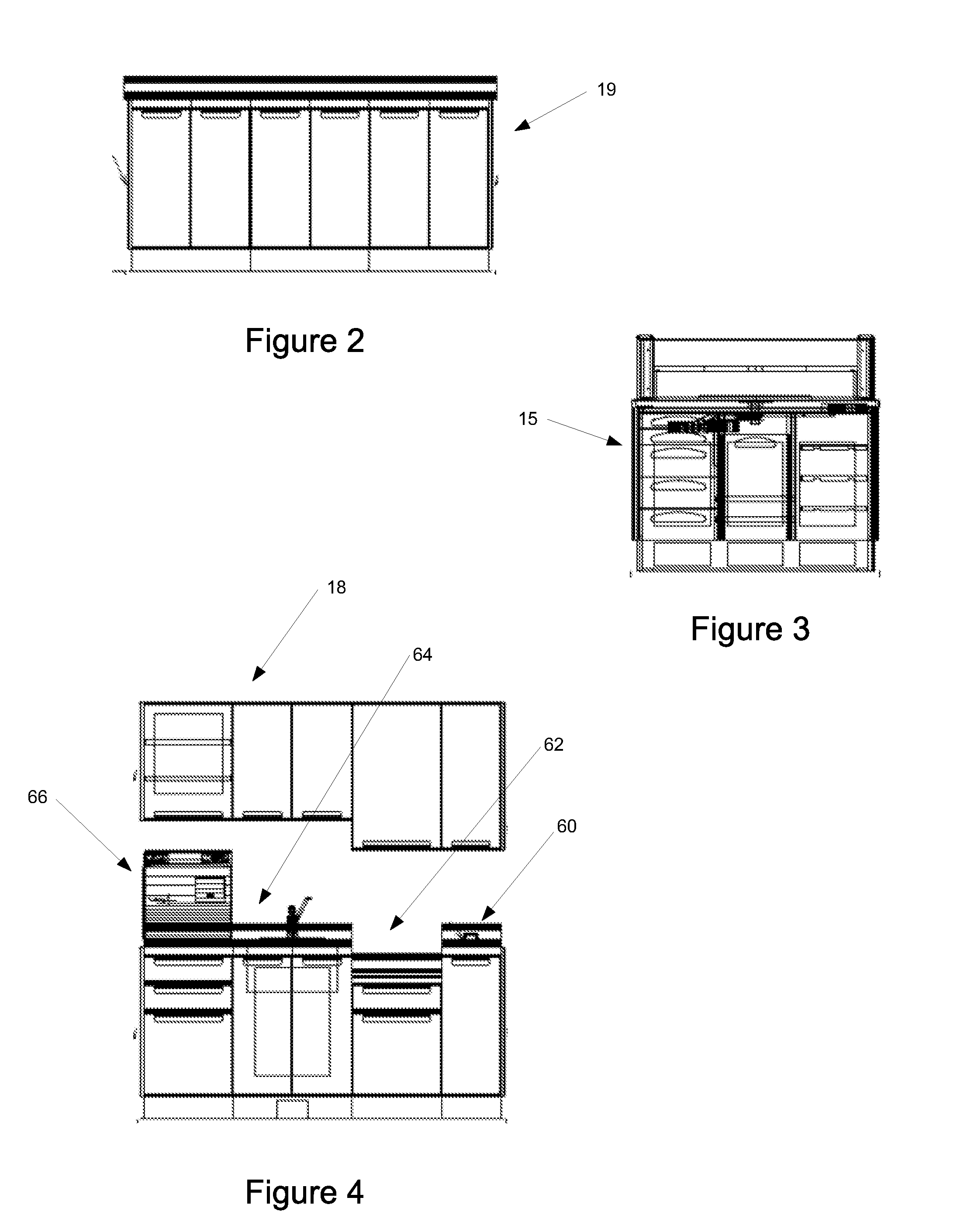
Referring now to the drawings and in particular to FIG. 1, the multi-function medical room 10 is shown in FIG. 1 as comprising room enclosure 12, treatment table 14, lighting unit 16, radiography assembly 17, cleaning system 18 and storage facility 19. The multi-function medical room can be placed within...


PUM


Abstract

A multi-function medical room comprising a room enclosure, a treatment table, a lighting assembly, a cleaning system and a power facility. The room enclosure includes a back wall, a front wall, a first side wall and a second side wall. A door is positioned on one of the walls. The treatment table is positioned within the room enclosure, and includes an upper body region, a torso region and a leg region. It is positionable into a substantially planar configuration to a configuration wherein the upper body region is rotated upwardly so as to be substantially perpendicular to the upper torso region, and wherein the leg region is rotated downwardly so as to be substantially perpendicular to the torso region. The lighting assembly has an arm with a first end coupled to a ceiling above the treatment table, and a second end coupled to a lamp. The arm is configured to position the lamp from the upper body region to the leg region of the treatment table, upon user movement of the same. The cleaning system extends along one of the walls of the room enclosure, and has sequentially positioned, a wiping region, a sink unit and an autoclave. The power facility extends along one of the walls of the room enclosure and includes a vacuum source and a source of compressed air.

Description

BACKGROUND OF THE DISCLOSURE1. Field of the DisclosureThe disclosure relates in general to a medical room, and more particularly, to a multi-function medical room that is configured for use for a number of different medical disciplines, at, for example a nursing home, an extended stay, or remote location. Such a facility is useful in situations wherein it may be difficult to take a patient to a hospital or doctors office, or a situation wherein it may be difficult to take individuals to a medical facility, but where a medical practitioner can more easily be brought to the remote location.2. Background ArtTypically, in a nursing home environment, when medical attention is needed, a patient or resident at the nursing home is prepared and transported, typically by bus to a remote facility, such as a medical office or hospital. Often, the preparation and transport of elderly patients, especially for less invasive, or non-invasive procedures, can pose some difficulty and risk. For exampl...

Claims


Application Information

Patent Timeline
Patent Type & Authority Applications(United States)
IPC IPC(8): E04H3/08
CPCE04H3/08E04H1/06E04H1/005
Inventor BOEKELOO, STUART W.
Owner BOEKELOO STUART W
Why Eureka
Try Eureka