System and method for leaking crack repair

Inactive Publication Date: 2011-11-17
STRUCTURAL GRP
View PDF20 Cites 15 Cited by
  • Summary
  • Abstract
  • Description
  • Claims
  • Application Information

AI Technical Summary

Benefits of technology

[0012]In use, a flexible insert in the form of an elastomeric, compressible seal is provided that is configured for insertion within and permanent attachment to a machined groove that extends above and along the path of a crack in a concrete structure. An existing crack in a concrete structure is machined to form a constant width and constant depth groove over the location of the original crack. The compressible seal is then inserted into the machined groove, with the sidewalls of the compressible seal being adhesively joined to the sidewalls of the machined groove. Preferably, the top side of the compressible seal is configured to, once installed, lie flush with the concrete wall face, although other configurations are suitable and may be used without departing from the spirit and scope of the invention. The bottom side of the compressible seal is configured to, once installed, create a grout-receiving space between the bottom of the compressible seal and the machined groove. Once the compressible seal is installed within the machined groove, a grout may be injected into the grout-receiving space to fill that space, and may likewise extend into at least a portion of the original crack itself, in turn providing a compressed but flexible and movable seal above the crack. The injection of such grout will prevent water from tracking along the length of the seal in the event that future movement of the crack leads to water reaching the seal at some location.

Problems solved by technology

Concrete structures, such as tunnels, pavements, bridges, foundations, and the like, are often prone to the development of cracks.
While cracks can more easily develop in concrete structures as a result of improper design and construction practices, all concrete structures will, regardless of construction techniques, have some tendency to develop cracks.
That tendency may increase as a result of particular mechanical loads on the concrete structure, settlement, shrinkage in both fresh and hardened concrete structures, temperature changes, corrosion, and the like.
Of course, the development of significant cracks in concrete structures can adversely affect the performance of such structures.
Each of these prior attempts, however, have had their respective shortcomings and have not been entirely suitable for the long term waterproof sealing of cracks that are prone to opening and closing over time.
A particular challenge exists with regard to the repair of concrete structures exposed to hydrostatic water pressure, such as many tunnels.
Water intrusion into cracks in concrete can accelerate corrosion of reinforcing steel and lead to deterioration of the concrete itself.
Control and repair of such cracks, while critical to maintaining the integrity of the structure, can be difficult.
However, injecting cracks with such fill materials often prove insufficient, as the seal provided by such material tends to fail as the crack opens and closes over time.
While potentially suitable for temporarily sealing small cracks in concrete, such application would not be suitable for the permanent, water-tight sealing of significant cracks in concrete structures, as the continuous expansion and contraction of the concrete would quickly break the seal formed by such material.
Once again, while potentially suitable for temporarily sealing small cracks in concrete, such application would not be suitable for the permanent, water-tight sealing of significant cracks in concrete structures, as the continuous expansion and contraction of the concrete would quickly break the seal formed by such material.
While such systems may be useful in providing a sealing joint between planar wall surfaces and similarly configured, finished joint faces, they are typically not suitable for use in sealing irregularly shaped cracks that may randomly form in the concrete structure.
Unfortunately, as the foregoing attempted solutions tend to fail once the crack opens, causing the injected material to break down and / or separate from the edges of the crack and thus allowing water intrusion to continue, they have not proven to be permanent solutions.

Method used


Image

  • System and method for leaking crack repair
  • System and method for leaking crack repair
  • System and method for leaking crack repair

Examples


Embodiment Construction

[0034]The following description is of a particular embodiment of the invention, set out to enable one to practice an implementation of the invention, and is not intended to limit the preferred embodiment, but to serve as a particular example thereof. Those skilled in the art should appreciate that they may readily use the conception and specific embodiments disclosed as a basis for modifying or designing other methods and systems for carrying out the same purposes of the present invention. Those skilled in the art should also realize that such equivalent assemblies do not depart from the spirit and scope of the invention in its broadest form.

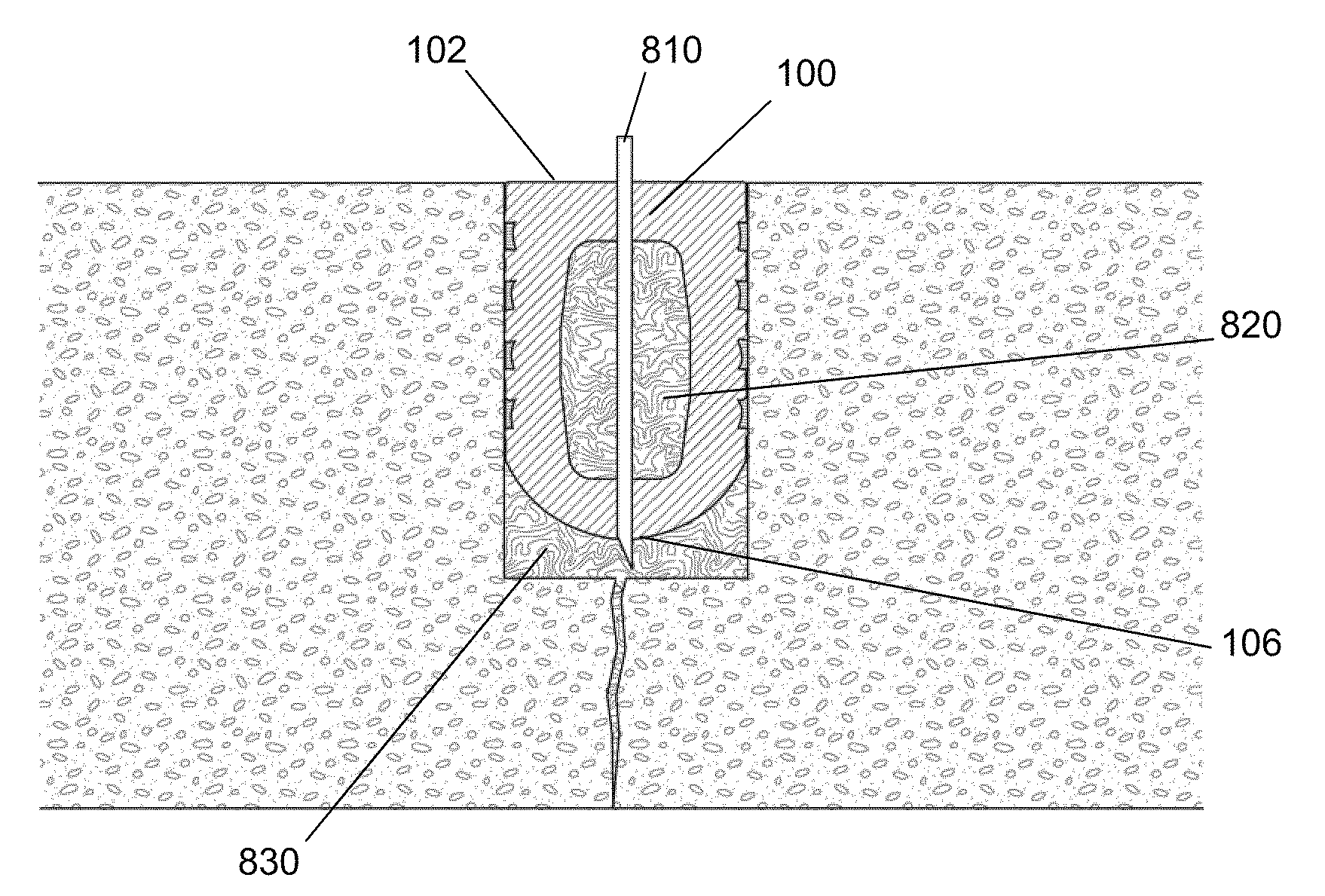
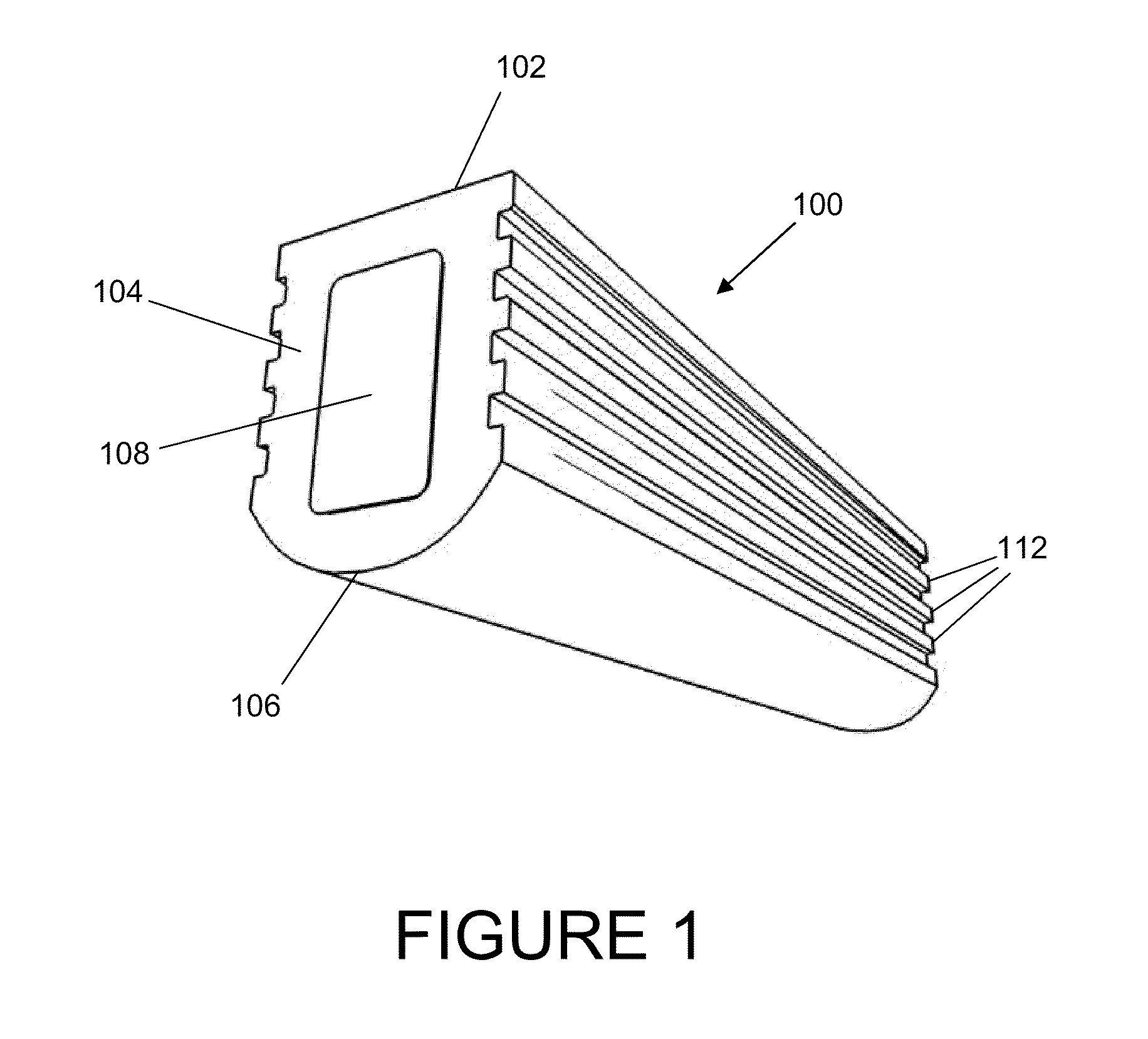
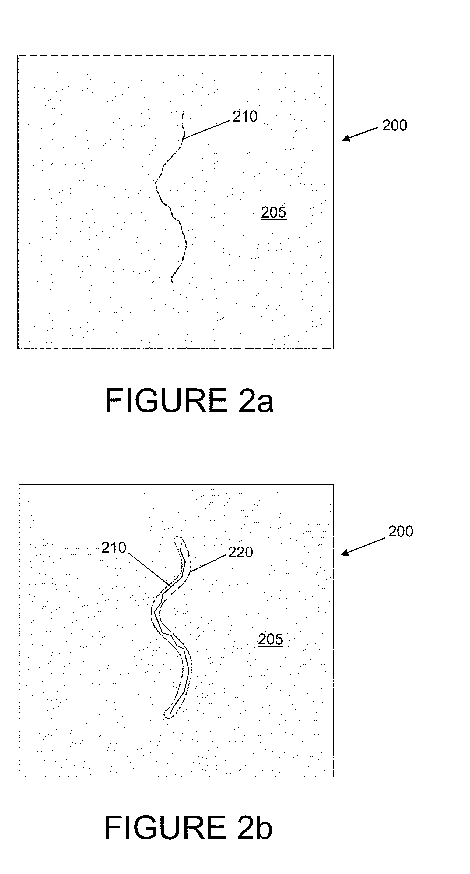
[0035]Disclosed is a system and method for providing a concrete crack repair system that is capable of providing a pressurized seal that continues to resist the ingress of water even as the crack continues to open and close over time. Such a solution may be particularly well suited for application to negative pressure side concrete waterproofing...


PUM


Abstract

Disclosed is a system and method for providing a concrete crack repair system that is capable of providing a pressurized seal that continues to resist the ingress of water even as the crack continues to open and close over time. A compressible seal is provided that may be inserted into and adhesively joined to a machined groove that follows the contour of the crack in the concrete surface. After its installation in the machined groove, grout may be injected into the machined groove below the compressible seal so as to fill the space between the compressible seal and the bottom of the machined groove, which grout may also flow into the groove that is adjacent the bottom of the machined groove, thus allowing pressurized grouting of the crack itself. The compressible seal may also include an interior, hollow chamber that may allow inflation of the compressible seal within the machined groove, thus forming a permanent pressurized seal above the crack.

Description

CROSS REFERENCE TO RELATED APPLICATION[0001]This application is based upon and claims priority from co-pending U.S. Provisional Patent Application Ser. No. 61 / 395,391 entitled “Novel Means of Sealing Cracks in Concrete to Stop the Penetration of Water,” filed with the U.S. Patent and Trademark Office on May 13, 2010 by the inventors herein, the specification of which is incorporated herein by reference.FIELD OF THE INVENTION[0002]This invention relates generally to the repair of cracks in concrete structures, and more particularly to systems and methods for permanently waterproofing leaking cracks in concrete that are subject to opening and closing over time.BACKGROUND[0003]Concrete structures, such as tunnels, pavements, bridges, foundations, and the like, are often prone to the development of cracks. Concrete contracts and expands with changes in moisture and temperature, and can deflect based on the load applied to the structure and the support conditions for the structure. While...

Claims


Application Information

Patent Timeline
IPC IPC(8): E04G23/02E04B1/66E04B1/682
CPCE04G23/0203E04B1/6812
Inventor EMMONS, PETER H.ANDERSON, BRENT D.
Owner STRUCTURAL GRP
Why Eureka
Try Eureka