
Closable Solar Collector

a solar collector and closed technology, applied in the field of solar collectors, can solve the problems of difficult transportation and storage of absorbing surfaces with a larger surface area, damage to absorbing surfaces, etc., and achieve the effect of convenient transportation and storag

Inactive Publication Date: 2011-11-17
LEADINWAY
View PDF6 Cites 23 Cited by
  • Summary
  • Abstract
  • Description
  • Claims
  • Application Information

AI Technical Summary

Benefits of technology

The main object of the present invention is to provide a closable solar collector that is convenient to transport and store.
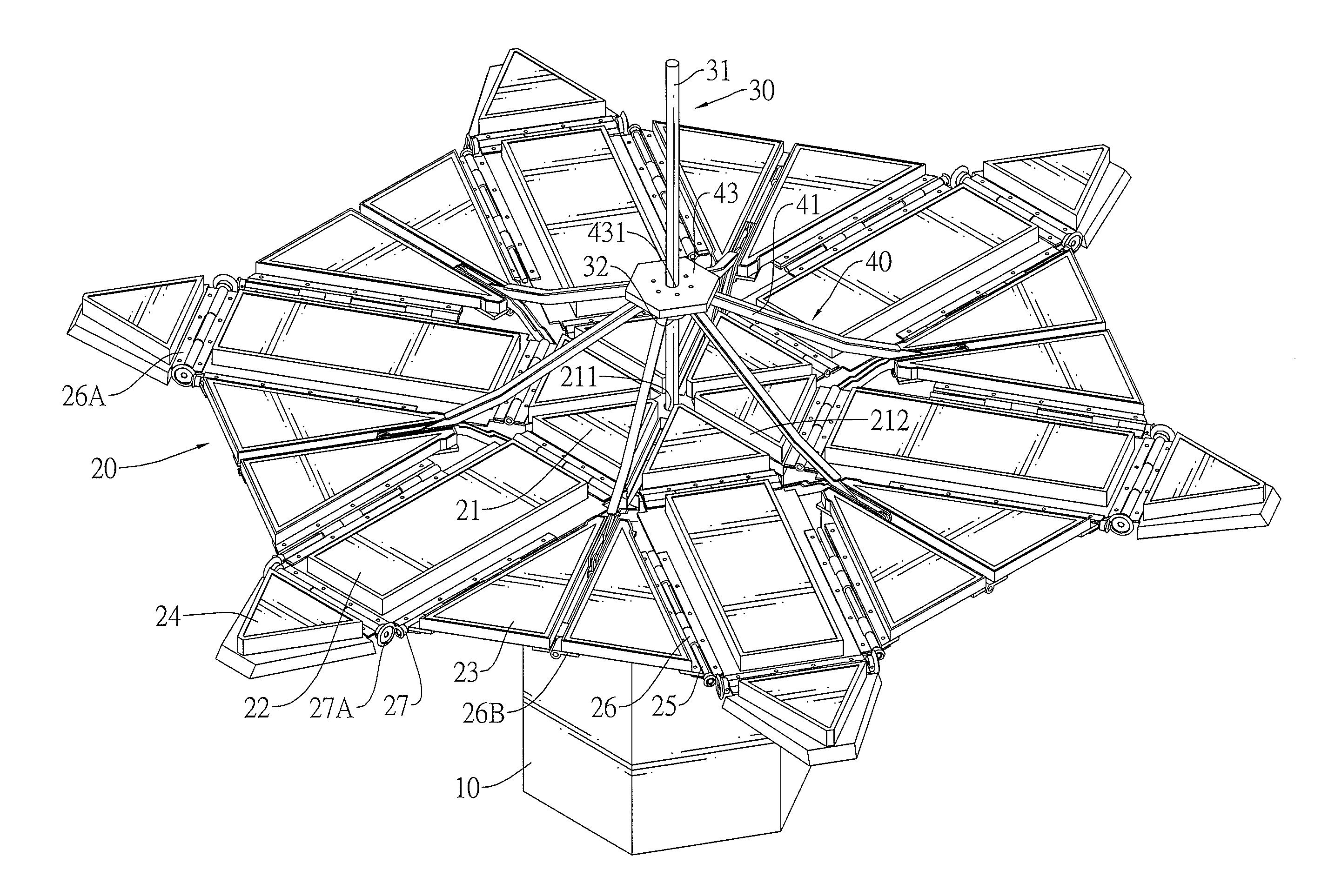
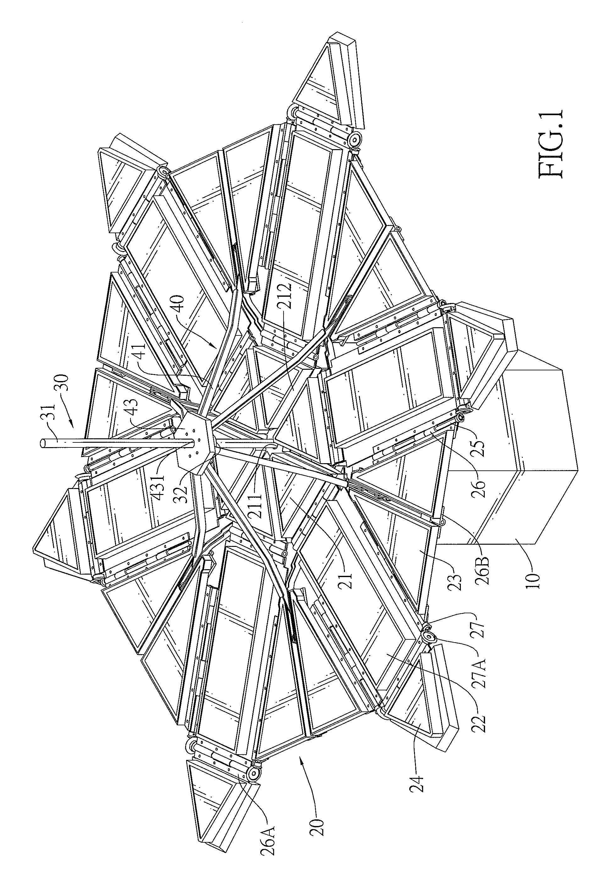
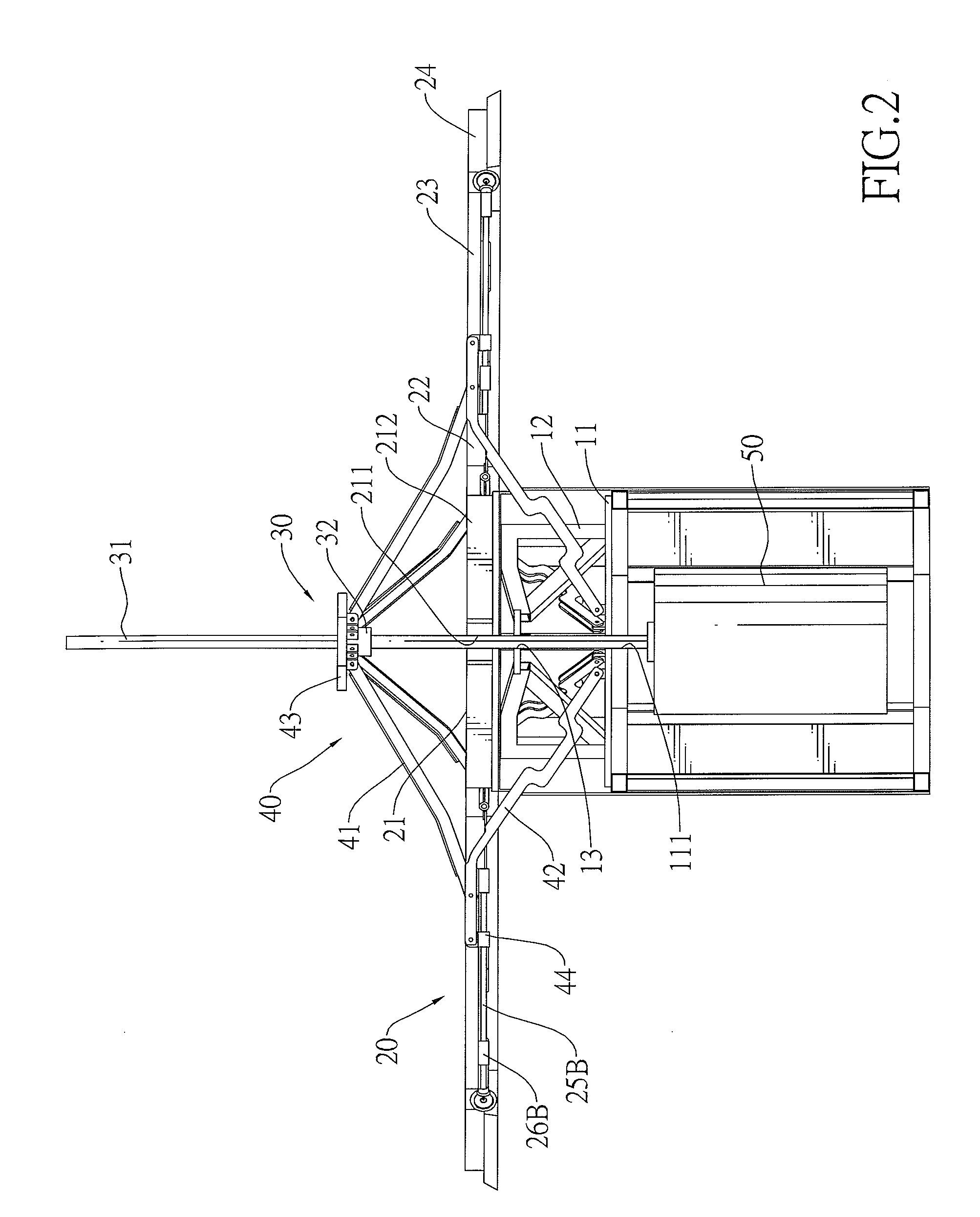
To achieve the objective, the closable solar collector in accordance with present invention comprises a stand, a solar panel body, a ball screw and a linking assembly. The solar panel body is mounted on the stand and has a base solar panel, multiple side solar panels and multiple folding solar panels. The side solar panels are mounted pivotally around the base solar panel. Every two folding solar panels are mounted pivotally between two adjacent side solar panels. The ball screw is mounted through the base solar panel and has a nut. The linking assembly is mounted pivotally between the nut and the stand and has multiple upper linking rods and multiple lower linking rods. Each lower linking rod has a top end mounted slidably between two adjacent folding solar panels. The ball screw is actuated to drive the linking assembly and the solar panel body to move so the solar panel body can be open or closed. Therefore, the solar collector is convenient and easy to use and store.

Problems solved by technology

However, the absorbing surface with a larger surface area is difficult to transport and store.
Besides, the absorbing surface is exposed all the time and consequently covering or storing the solar panel during the sudden onset of a typhoon, rain or snow may be difficult or impossible, which could easily lead to the absorbing surface being damaged.

Method used


Image

  • Closable Solar Collector
  • Closable Solar Collector
  • Closable Solar Collector

Examples


Embodiment Construction

With reference to FIGS. 1 and 2, a closable solar collector in accordance with the present invention comprises a stand (10), a solar panel body (20), a ball screw (30) and a linking assembly (40).

The stand (10) is hollow, has a cavity, a board (11) and a frame (12). The board (11) is mounted inside the cavity of the stand (10) and has a central hole (111). The frame (12) is mounted on the board (11) and has a central hole (13) aligns with the central hole (111) of the board (11). A motor (50) may be mounted inside the stand (10) under the board (11) and has an output shaft.

With further reference to FIGS. 3 and 4, the solar panel body (20) is mounted on the stand (10) and has a base solar panel (21), multiple side solar panels (22), multiple folding solar panels (23), multiple top solar panels (24), multiple side hinges (26), multiple side bevel gears (27), multiple top hinges (26A), multiple top bevel gears (27A) and multiple folding hinges (26B). The base solar panel (21) is mounte...


PUM


Abstract

The closable solar collector has a stand, a solar panel body, a ball screw and a linking assembly. The solar panel body is mounted on the stand and has a base solar panel, multiple side solar panels and multiple folding solar panels. The side solar panels are mounted pivotally around the base solar panel. Every two folding solar panels are mounted pivotally between two adjacent side solar panels. The ball screw is mounted through the base solar panel. The linking assembly is mounted pivotally between the ball screw and the stand and has multiple upper linking rods and multiple lower linking rods. The ball screw is actuated to drive the linking assembly and the solar panel body to move so the solar panel body can be open or closed. Therefore, the solar collector is convenient and easy to use and store.

Description

BACKGROUND OF THE INVENTION1. Field of the InventionThe present invention relates to a solar collector, and more particularly to a closable solar collector that is convenient to store and transport.2. Description of the Prior ArtsA solar collector is a device for collecting energy from the sun direct use or storage. A conventional solar collector comprises at least one solar panel mounted securely on a frame and mounted in a place facing the sky like a roof, or a square other altitudes. The solar panel has multiple solar cells mounted securely on the solar panel to form an absorbing surface. The absorbing surface absorbs solar energy striking the absorbing surface and transformed solar energy into electricity for commercial and residential applications. The absorbing surface with a larger surface area absorbs more solar energy to result in more power being provided by the solar collector.However, the absorbing surface with a larger surface area is difficult to transport and store. B...

Claims


Application Information

Patent Timeline
IPC IPC(8): F24J2/46
CPCH02S30/20F24J2/36F24S20/50Y02E10/50
Inventor CHU, RAYMOND
Owner LEADINWAY
Learn More