Anti-scalding device with a speedy venting effect

Inactive Publication Date: 2011-11-17
XIAMEN EASO CO LTD
View PDF6 Cites 6 Cited by
  • Summary
  • Abstract
  • Description
  • Claims
  • Application Information

AI Technical Summary

Benefits of technology

[0005]The object of the present invention is to provide an anti-scalding device with a speedy venting effect for preventing users from being scaled and for a sensor to timely sense the lowered water temperature, so that a channel is dredged and the using convenience is promoted.
[0009]A casing pipe rotatively and densely disposed on the main body is engaged with the housing. A torsion spring is installed between the casing pipe and the main body. Openings, whose amount is arranged in accordance with a number of the venting holes of the connecting portion, are defined on the casing pipe. A water cavity is correspondingly formed between the housing of the opening and the casing pipe. A rotation of the housing and the casing pipe corresponding to the main body controls an open-close state of the venting channel between the venting holes.
[0010]By means of the venting holes being disposed on the main body, the axial movement or the rotation of the housing to the main body allows the blocked water with a high temperature in the channel to be speedily discharged. Thereby, the sensor is able to timely sense the water with a normal temperature so as to dredge the channel of the outlet. As a result, the operating time of the sensor is shortened, which conduces to a convenient utilization for users.

Problems solved by technology

During shower, users are easily scaled in view of the unstable water pressure between the cold water and the hot water or due to the improper adjustment in the mixed water that both result in an over-heating water temperature.
As a result, the heat-sensing member is unable to timely sense the succeeding lowered water temperature, and the channel cannot be dredged in a short time.
Therefore, users need to wait a long time for the water with a normal temperature, which is quite inconvenient.
Especially, if the waiting is happened in the winter time, users may easily get a cold.

Method used


Image

  • Anti-scalding device with a speedy venting effect
  • Anti-scalding device with a speedy venting effect
  • Anti-scalding device with a speedy venting effect

Examples


Embodiment Construction

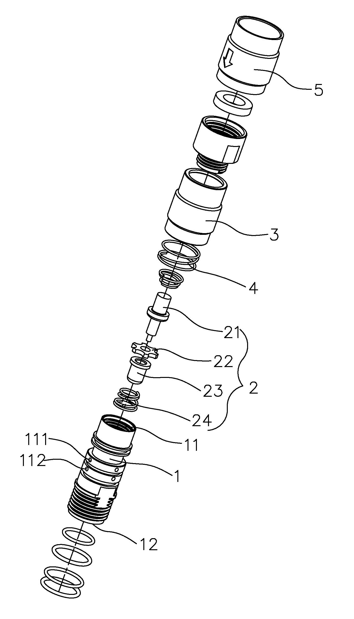
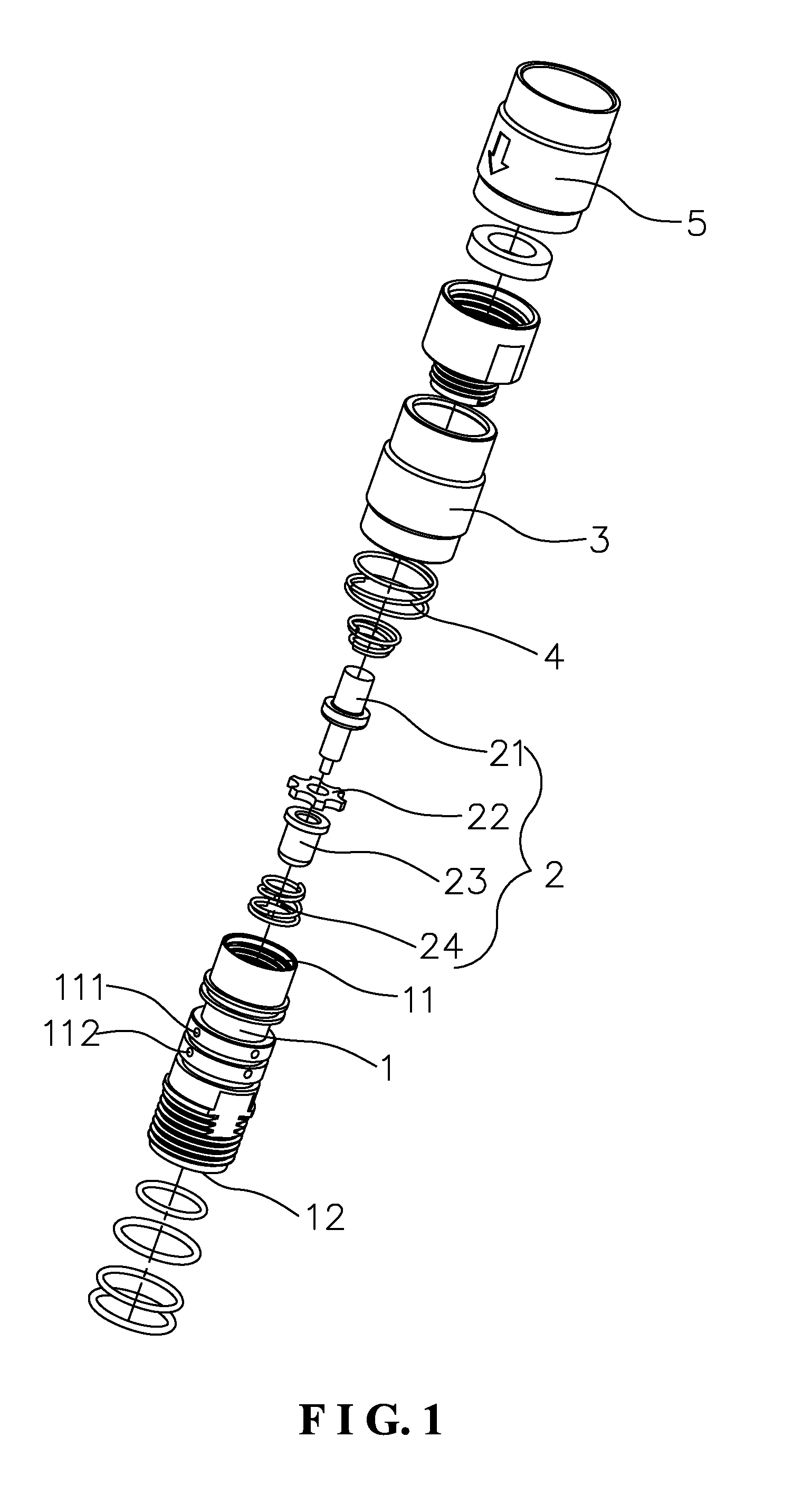
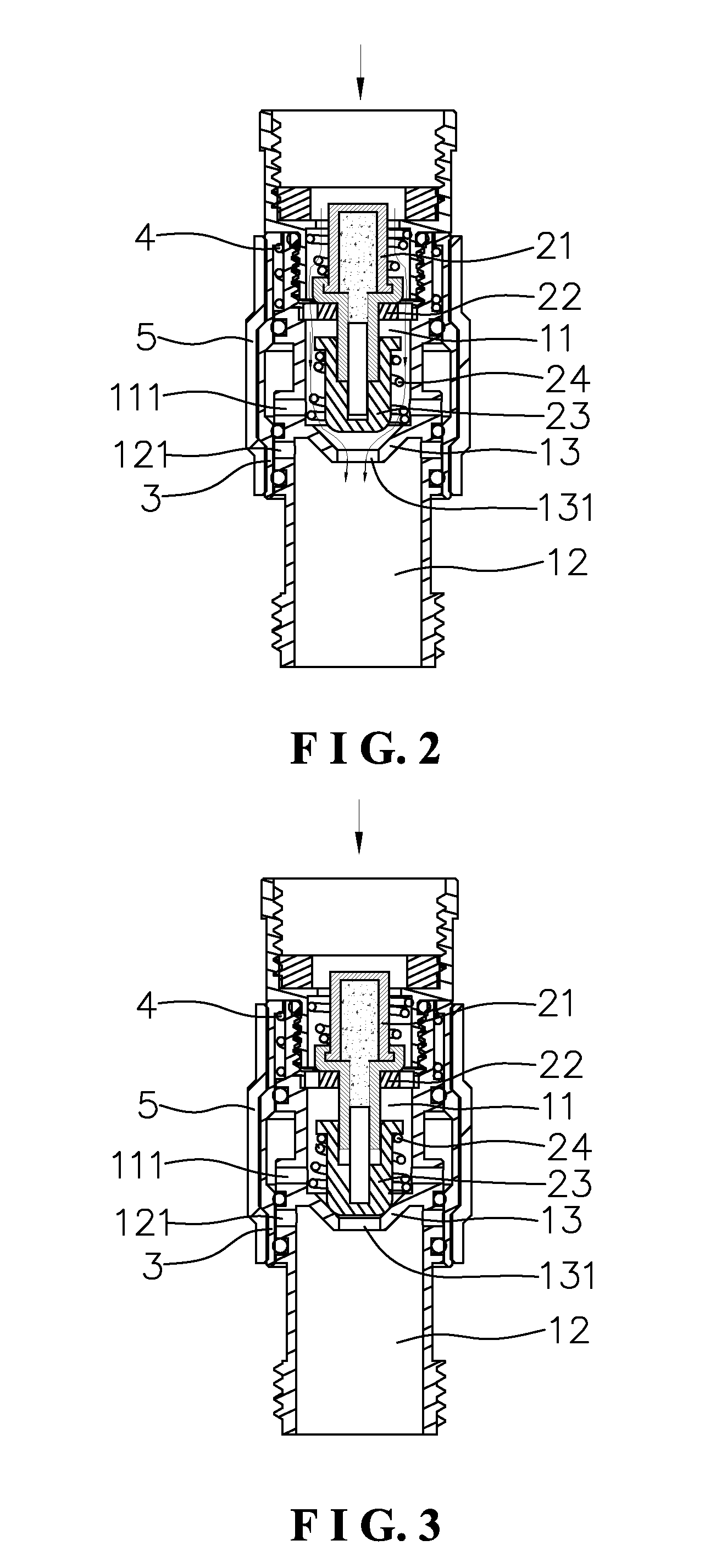
[0021]Referring to FIGS. 1 to 5, an anti-scalding device with a speedy venting effect is disposed on a channel of an outlet. The present invention substantially comprises a main body 1, a sensor 2, and a housing 3. The main body 1 adopts a hollow pipe where a first cavity 11 and a second cavity 12 are upward and downward separated and communicated with each other. A first necking portion 13 with a water hole 131 is formed at a bottom of the first cavity 11. The first cavity 11 links with an inlet channel. The second cavity 12 links with an outlet. The intercommunication between the first and second cavities 11, 12 is achieved via the water hole 131. At least one venting hole 111, 121 is arranged on a pipe wall of the first cavity 11 and the second cavity 12, respectively. As shown in the figures, two through holes are symmetrically defined thereon. The sensor 2 similarly adopts the existing techniques. Namely, the sensor 2 is serially composed of a heat-sensing member 21, a supporti...


PUM


Abstract

An anti-scalding device with a speedy venting effect comprises a main body, a sensor, and a housing. A first cavity and a second cavity intercommunicated are formed in the main body. The first cavity communicates with an inlet channel, and a first necking portion with a water hole is formed at a bottom of the first cavity. The second cavity communicates with an outlet. At least one venting hole is defined on pipe walls of the first cavity and the second cavity, respectively. The sensor is arranged in the first cavity of the main body, correspondently located above the venting hole. The housing is densely sealed on the main body but movable thereon. Axially moving or rotating the housing to the main body allows the water with a high temperature obstructed in the channel to be swiftly discharged. Thereby, the sensor timely senses the water with a regular temperature to dredge the channel of the outlet. That is, the operating time of the sensor is shortened, and it is convenient for users.

Description

BACKGROUND OF THE INVENTION[0001]1. Field of the Invention[0002]The present invention relates to a shower device, in particularly to an anti-scalding device with a speedy venting effect applied to the shower device.[0003]2. Description of the Related Art[0004]During shower, users are easily scaled in view of the unstable water pressure between the cold water and the hot water or due to the improper adjustment in the mixed water that both result in an over-heating water temperature. In order to prevent such a dangerous situation, manufacturers install an anti-scalding device on a channel of an outlet. Generally, the anti-scalding device utilizes a heat-sensing member to sense the variation of the water temperature. While the water temperature is over a predetermined temperature set in the heat-sensing member, an element contained in the heat-sensing member, the chemical wax, accordingly expands in view of the heat. Thereby, the expanding chemical wax pushes a propping shaft to block ...

Claims


Application Information

Patent Timeline
IPC IPC(8): F16K17/38
CPCF16K31/002Y10T137/7737
Inventor LI, SENYI
Owner XIAMEN EASO CO LTD
Why Eureka
Try Eureka