Fall Protection Arrangement

a technology of protection arrangement and braking mechanism, which is applied in the direction of safety belts, sports equipment, cleaning equipment, etc., can solve the problems of product failure, variability in performance, galling or uneven wear of the braking mechanism, etc., and achieve the effect of reducing or eliminating the effects of galling or uneven wear and reducing the variability of braking performan

Active Publication Date: 2011-11-17
MSA TECH
View PDF9 Cites 34 Cited by
  • Summary
  • Abstract
  • Description
  • Claims
  • Application Information

AI Technical Summary

Benefits of technology

[0011]Generally, the present invention provides a fall protection arrangement that addresses or overcomes some or all of the drawbacks and deficiencies associated with known devices and arrangements in the field of fall protection and worker safety. Preferably, the present invention provides a fall protection arrangement that reduces or eliminates the effects of galling or uneven wear in certain components of a fall protection device. Preferably, the present invention provides a fall protection arrangement that reduces variability in braking performance in a fall protection device. Preferably, the present invention provides a fall protection arrangement that meets regulatory standards in a reliable and cost effective manner.
[0014]In a still further preferred and non-limiting embodiment, the present invention provides a fall protection arrangement including a rotatable hub and a lifeline having a first end attached to the hub and a second end configured for removable attachment to a user. The hub includes an outer surface around which the lifeline is wound, and the lifeline extends under a protrusion, such that a first portion of the lifeline extends from the first end of the lifeline to the protrusion, and a second portion extends from the protrusion to the second end of the lifeline. The protrusion is configured or arranged to retain the lifeline and, under certain conditions, fracture and release the first portion of the lifeline. An engagement mechanism is configured or arranged to directly or indirectly prevent rotation of the hub upon activation, and a braking arrangement is configured to slow the rotation of the hub upon activation of the engagement mechanism.

Problems solved by technology

Therefore, while many different models and arrangements of SRLs exist, one common problem that arises with the braking mechanism is the galling or uneven wear that occurs in connection with portions of the braking mechanism, such as the friction pads.
This galling effect leads to variability in performance due to the variability in contact and pressure points between adjacent surfaces in the mechanism.
Further, this increased variability may lead to product failure and reduced effectiveness in operation.
Accordingly, large force and extension variations (which result from galling and uneven wear) require designers to develop products with tight design limits to account for this variation.

Method used


Image

  • Fall Protection Arrangement
  • Fall Protection Arrangement
  • Fall Protection Arrangement

Examples


Embodiment Construction

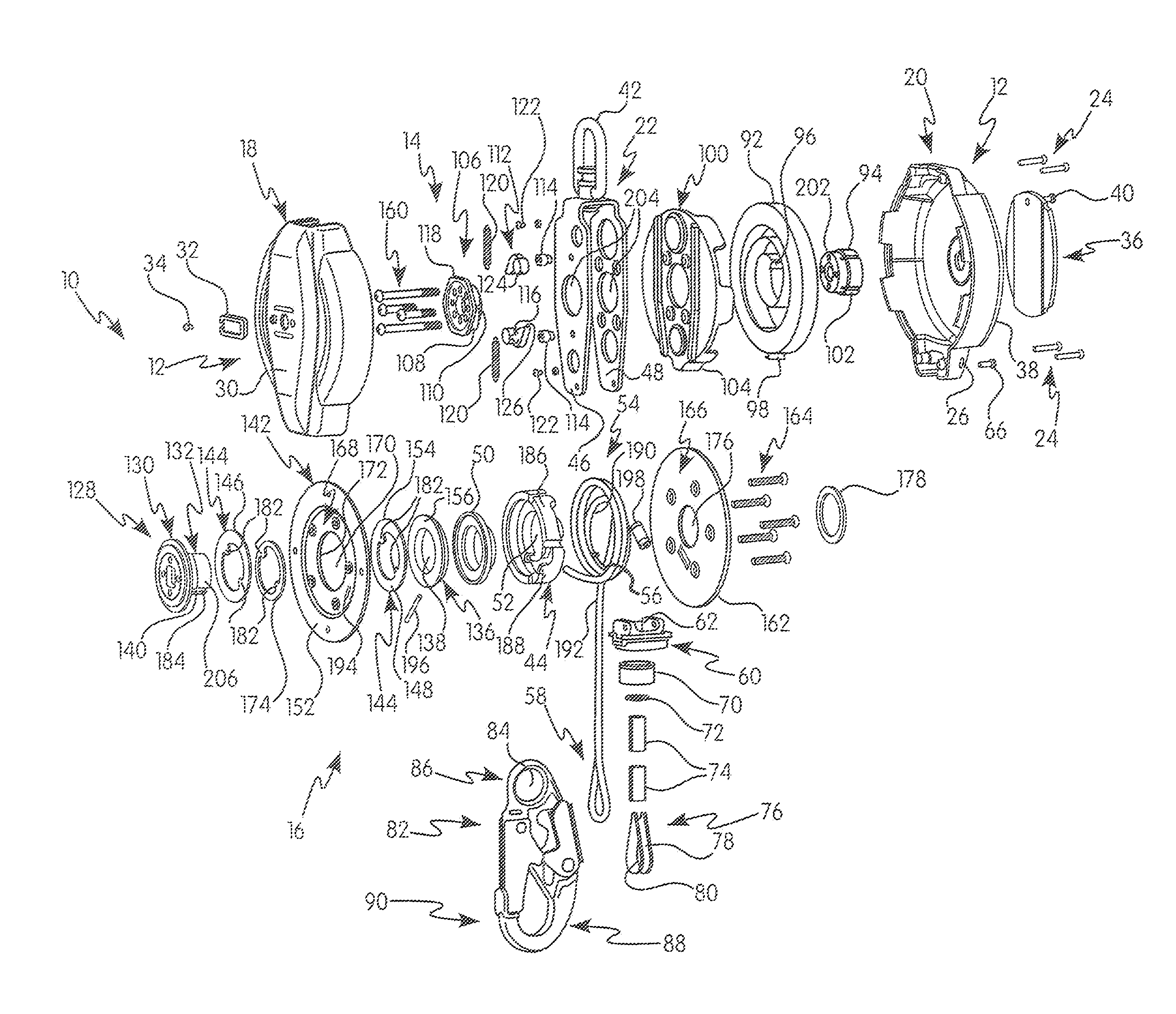
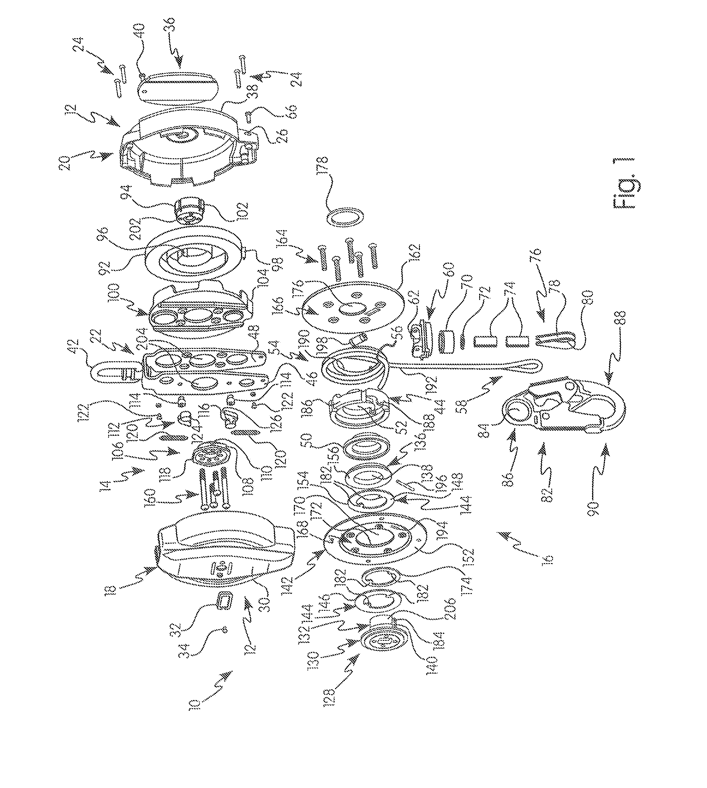
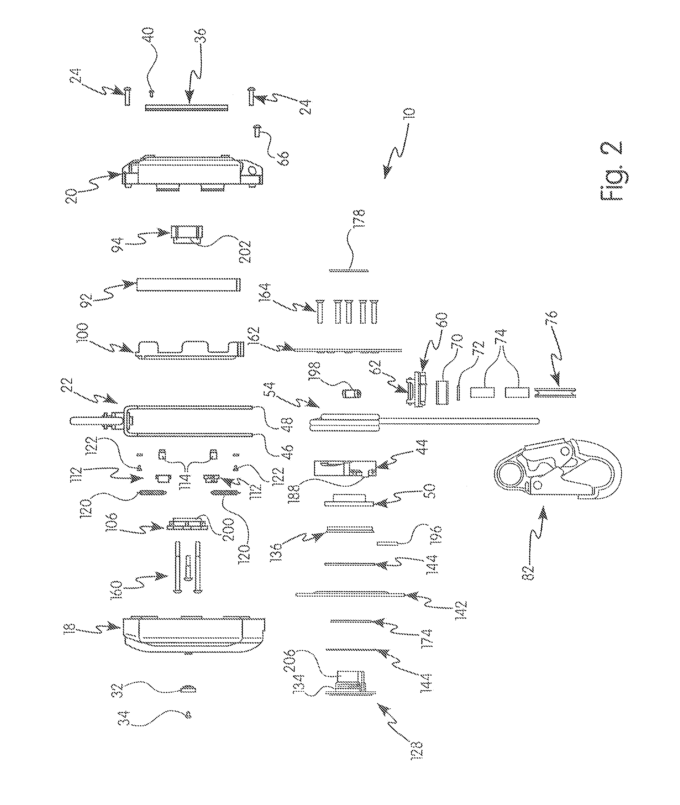
[0023]For purposes of the description hereinafter, the terms “end”, “upper”, “lower”, “right”, “left”, “vertical”, “horizontal”, “top”, “bottom”, “lateral”, “longitudinal” and derivatives thereof shall relate to the invention as it is oriented in the drawing figures. However, it is to be understood that the invention may assume various alternative variations and step sequences, except where expressly specified to the contrary. It is also to be understood that the specific devices and processes illustrated in the attached drawings, and described in the following specification, are simply exemplary embodiments of the invention. Hence, specific dimensions and other physical characteristics related to the embodiments disclosed herein are not to be considered as limiting. Further, it is to be understood that the invention may assume various alternative variations and step sequences, except where expressly specified to the contrary.

[0024]The present invention is directed to a fall protect...


PUM


Abstract

A fall protection arrangement including a rotatable hub and a lifeline having a first end attached to the hub and a second end for removable attachment to a user, an engagement mechanism to prevent rotation of the hub upon activation, and a braking arrangement to brake the payout of the lifeline during a fall event.

Description

CROSS REFERENCE TO RELATED APPLICATIONS[0001]This application claims the benefit of priority from Provisional Patent Application No. 61 / 333,984, filed May 12, 2010, the contents of which are incorporated herein in its entirety.BACKGROUND OF THE INVENTION[0002]1. Field of the Invention[0003]The present invention relates generally to safety systems and arrangements and in particular to a fall protection arrangement, such as a controlled descent device, including self-retracting lanyards and the like, which may be used in connection with a harness to protect the wearer from a sudden, accelerated fall arrest event.[0004]2. Description of the Related Art[0005]As is known in the art of safety systems and processes, a lanyard, such as a self-retracting lanyard (SRL), are used for fall protection in both industrial environments, as well as in connection with recreational activities. Self-retracting lanyards have numerous industrial end uses, including, but not limited to, construction, manu...

Claims


Application Information

Patent Timeline
Patent Type & Authority Applications(United States)
IPC IPC(8): A62B35/00A47L3/04A62B1/08
CPCA62B35/0093A62B1/10
Inventor HETRICH, MITCHELL H.LOSOS, DAVID J.
Owner MSA TECH
Why Eureka
Try Eureka