Radio wave receiving apparatus and position calculating method

Inactive Publication Date: 2011-11-17
NEC CORP
View PDF6 Cites 10 Cited by
  • Summary
  • Abstract
  • Description
  • Claims
  • Application Information

AI Technical Summary

Benefits of technology

[0023]It is an object of the present invention to provide a radio wave receiving apparatus and a position calculating method which are capable of easily receiving radio waves regardle

Problems solved by technology

However, it is theoretically infeasible to realize an antenna that is omnidirectional in a strict sense.
In a system such as E-911, therefore, the terminal of the caller may not be able to receive radio waves from the GPS satellites, and hence its position may not be determined.
The user needs to adjust the attitude and bearing of cellular phone 100 for better reception of GPS signals, giving rise to a problem in that the usage of cellular phone 100 is limited when it utilizes a GPS.
Consequently, the antenna apparatus according to the second background art needs a complex mechanism for adjusting the angle of elevation and the bearing of the ante

Method used


Image

  • Radio wave receiving apparatus and position calculating method
  • Radio wave receiving apparatus and position calculating method
  • Radio wave receiving apparatus and position calculating method

Examples


Example

First Exemplary Embodiment

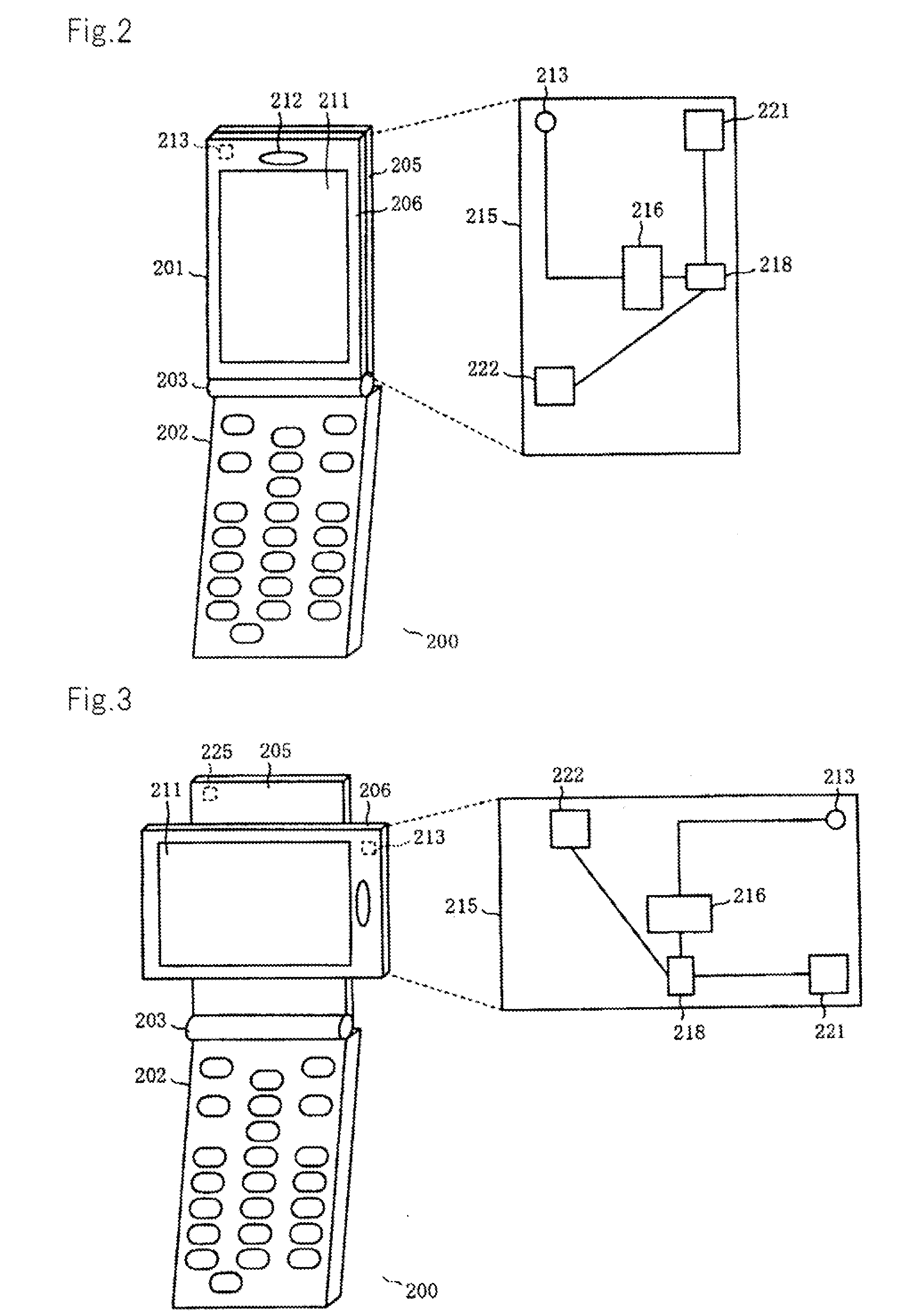
[0053]FIG. 2 is a perspective view showing an example of the appearance of a radio wave receiving apparatus according to a first exemplary embodiment, and FIG. 3 is a perspective view showing the manner in which a rotational member shown in FIG. 2 is rotated 90 degrees.

[0054]According to the first exemplary embodiment, a radio wave receiving apparatus for receiving radio waves from GPS satellites or the like comprises, by way of example, foldable cellular phone 200 including first body 201 and second body 202, shown in FIG. 2, which are openably and closably connected to each other by hinge mechanism 203.

[0055]First body 201 comprises base 205 connected to second body 202 by hinge mechanism 203 and rotational member 206 rotatably mounted on base 205.

[0056]Base 205 has a rotational shaft, not shown, near its center, and rotational member 206 is mounted on the rotational shaft so as to be rotatable about 90 degrees with respect to base 205, as shown in FIG. 3...

Example

Second Exemplary Embodiment

[0089]FIG. 7 is a perspective view showing an example of the appearance of a radio wave receiving apparatus according to a second exemplary embodiment, and FIG. 8 is a perspective view showing the manner in which a rotational member shown in FIG. 7 is slid. Those components shown in FIGS. 7 and 8 which are identical to the components of the cellular phone shown in FIGS. 1 and 2 are denoted by identical reference characters, and their description will be omitted hereinbelow.

[0090]According to the second exemplary embodiment, as with the first exemplary embodiment, a radio wave receiving apparatus for receiving radio waves from GPS satellites or the like comprises, by way of example, foldable cellular phone 200A including first body 201A and second body 202, shown in FIG. 7, which are openably and closably connected to each other by hinge mechanism 203A.

[0091]With cellular phone 200A according to the second exemplary embodiment, when rectangular display 211 ...

Example

Third Exemplary Embodiment

[0103]FIG. 11 is a perspective view showing an example of the appearance of a radio wave receiving apparatus according to a third exemplary embodiment, and FIG. 12 is a perspective view of an example of the structure of an angle-of-elevation changer shown in FIG. 11. Those components shown in FIG. 11 which are identical to the components of the cellular phone shown in FIG. 2 are denoted by identical reference characters, and their description will be omitted hereinbelow.

[0104]According to the third exemplary embodiment, as with the first exemplary embodiment and the second exemplary embodiment, a radio wave receiving apparatus for receiving radio waves from GPS satellites or the like comprises, by way of example, foldable cellular phone 200C including first body 201C and second body 202, shown in FIG. 11, which are openably and closably connected to each other by hinge mechanism 203C.

[0105]Cellular phone 200C has a configuration including angle-of-elevation...


PUM


Abstract

A radio wave receiving apparatus includes a plurality of antennas disposed on a circuit board, the plurality of antennas having radiation patterns with different bearings and which indicate a directivity of said antennas upon receipt of radio waves, a storage unit for storing information of the radiation patterns of the plurality of antennas, a detector for detecting a change in the attitude of the circuit board, and a controller for determining a distribution ratio for reception signals received by the plurality of antennas based on the information stored in the storage unit which corresponds to the attitude of the circuit board detected by the detector.

Description

TECHNICAL FIELD[0001]The present invention relates to a radio wave receiving apparatus and a position calculating method which are suitable for use in GPS (Global Positioning System).BACKGROUND ART[0002]A GPS is a three-dimensional positioning system for identifying the present position of a user using radio waves from a plurality of artificial satellites (hereinafter referred to as GPS satellites) orbiting around the earth. The GPS uses a GPS receiver for calculating its own position based on map data preset therein and received GPS signals. The GPS receiver is installed in a terminal such as a cellular phone or the like and can also be used for navigation. The terminal with the GPS receiver installed therein can be used to report emergencies such as incidents and accidents because its position can easily be transmitted to someone that the terminal has called. In the U.S., there has been proposed a system wherein a GPS receiver is installed in a CDMA (Code Division Multiple Access)...

Claims


Application Information

Patent Timeline
IPC IPC(8): G01S19/42H01Q3/08H04B17/00H01Q3/04G01S19/35
CPCG01S19/36H01Q1/243H04B7/0805H01Q21/28H01Q3/08
Inventor SHIBOHTA, HIDETO
Owner NEC CORP
Why Eureka
Try Eureka