Beam direction controlling device and light-output device

a technology of beam direction and control device, which is applied in the direction of fixed installation, lighting and heating apparatus, instruments, etc., can solve the problems of not being as obvious as currently, and achieve the effect of simple and robust control

Inactive Publication Date: 2011-11-17
KONINKLIJKE PHILIPS ELECTRONICS NV
View PDF6 Cites 34 Cited by
  • Summary
  • Abstract
  • Description
  • Claims
  • Application Information

AI Technical Summary

Benefits of technology

In view of the above-mentioned and other drawbacks of the prior art, a general object of the present invention is to provide an improved beam direction co

Problems solved by technology

For spotlights, however, the advantages are currently not as obvious, because the mechanical arrangements needed for controlling the direction of

Method used


Image

  • Beam direction controlling device and light-output device
  • Beam direction controlling device and light-output device
  • Beam direction controlling device and light-output device

Examples


first embodiment

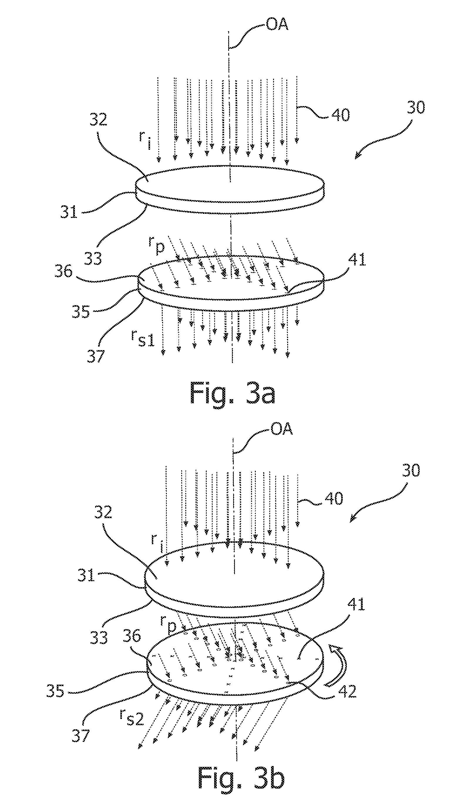
FIGS. 4a-b schematically illustrate the beam direction controlling device according to the present invention in different beam direction controlling states.

In FIGS. 4a-b, the first 46 and second 47 optical elements comprised in the beam direction controlling device 45 are provided in the form of prism plates, or prism foils, as is schematically indicated in the figures.

Such prism plates or foils are currently used in liquid crystal displays, LCDs, to aim the image output by the LCD in a given, fixed direction towards the expected position of a viewer.

By arranging two such prism plates in the manner indicated in FIGS. 4a-b, both the azimuth angle and the polar angle of the light-beam can be determined at will (within a certain polar angular range) by appropriately rotating the first 46 and second 47 optical elements.

In both FIG. 4a and FIG. 4b, the first optical element 46 is oriented in such a way that the incident light-rays 40 are redirected from the initial direction ri to the pr...

second embodiment

FIGS. 6a-b schematically illustrate the beam direction controlling device according to the present invention in different beam direction controlling states.

In FIGS. 6a-b, the first 61 and second 62 optical elements comprised in the beam direction controlling device 60 comprise lenticular arrays, as is schematically indicated in the figures.

By arranging two lenticular arrays in the manner indicated in FIGS. 6a-b, both the azimuth angle and the polar angle of the light-beam can be determined at will (within a certain polar angular range) by appropriately laterally translating the second optical element 62 in relation to the first optical element 61.

Since each lenticular 63 comprised in the first optical element 61 in FIG. 6a is a positive lens, the incident light hitting a lenticular 63 will be converged by the lenticular 63.

Considering a plurality of parallel light-rays 40, each hitting a respective lenticular 63 in a given position in an incident direction ri, each of these light-ra...

third embodiment

Finally, with reference to FIGS. 13a-b, the beam direction controlling device according to the present invention will now be described.

As can be seen in FIGS. 13a-b, the beam-direction controlling device 80 according to the present third embodiment differs from the previously described beam direction controlling devices in that a third optical element 81, in the form of a third lenticular array in between the first 61 and second 62 optical elements (referring also to FIG. 8). The focal length of the lenticulars 82 in the third lenticular array is chosen such that the third lenticular array 81 images the first lenticular array 61 onto the second lenticular array 62. Preferentially, the third lenticular array 81 is placed in the focal plane of the first lenticular array 61 which coincides with the focal plane of the second lenticular array 62.

As is illustrated in FIG. 13a, the function of the lenticulars 82 in the third lenticular array 81 is to make a point-to point image of the lent...


PUM


Abstract

A beam direction controlling device (22; 30; 45; 60; 80), for controlling a direction of a light-beam emitted by a light-source (21) and passing through the beam direction controlling device (22; 30; 45; 60; 80). The beam direction controlling device comprises a first optical element (23, 31; 46; 61) having first (32) and second (33) opposing faces and being configured to change a direction of a plurality of parallel light-rays (40) incident on the beam direction controlling device (22; 30; 45; 60; 80) in an incident direction (ri) at the first face (32) of the first optical element (23, 31; 46; 61) to a primary direction (rp), different from the incident direction (ri), at the second face (33) of the first optical element (23, 31; 46; 61); and a second optical element (24, 32; 47; 62) having first (36) and second (37) opposing faces, the second optical element (24, 32; 47; 62) being arranged with the first face (36) of the second optical element (24, 32; 47; 62) facing the second face (33) of the first optical element (23, 31; 46; 61), the second optical element (24, 32; 47; 62) being configured to change a direction of the plurality of light-rays from the primary direction (rp) at the first face (36) of the second optical element (24, 32; 47; 62) to a secondary direction (rs) at the second face (37) of the second optical element (24, 32; 47; 62) depending on points (41) of incidence of the light-rays on the first face (36) of the second optical element (24, 32; 47; 62). The beam direction controlling device is configured to allow relative movement between the first and second optical element for controlling the points of incidence of the light rays on the first face of the second optical element, thereby enabling control of the direction of the light-beam.

Description

FIELD OF THE INVENTIONThe present invention relates to a beam direction controlling device, and to a light-output device comprising such a beam direction controlling device.BACKGROUND OF THE INVENTIONDownlights and spotlights are in very widespread use by architects, interior designers as well as end-users for creating a desired interior style.Downlights are generally used for general illumination purposes and usually produce a relatively broad beam, whereas spotlights are typically aimed at a certain target by tilting and rotating the spotlight.Recently, advances in lighting technology, especially in the field of light-emitting diodes (LEDs) and LED-based luminaires, have enabled flat and compact light-output devices, such as luminaires, which are easier to install and more compact and unobtrusive than conventional lighting systems.For downlights, the use of this new type of flat luminaires is relatively straight-forward. For spotlights, however, the advantages are currently not as...

Claims


Application Information

Patent Timeline
IPC IPC(8): F21V14/04F21V14/00
CPCF21V5/002F21V5/007F21V14/06F21V14/04F21V5/045F21S8/04F21V5/005F21V5/008G02B3/005G02B3/0056G02B3/0062G02B5/045G02B19/0009G02B19/0014G02B19/0033G02B26/0883G02B26/108F21V5/004
Inventor VISSENBERG, MICHEL C. J. M.PIJLMAN, FETZEKRIJN, MARCELLINUS P. C. M.DE ZWART, SIEBE T.IJZERMAN, WILLEM L.
Owner KONINKLIJKE PHILIPS ELECTRONICS NV
Why Eureka
Try Eureka