A method and a device for cleaning an electrostatic precipitator

An electrostatic precipitator, cleaning technology

Inactive Publication Date: 2019-02-01
GENERAL ELECTRIC TECH GMBH
View PDF14 Cites 0 Cited by
  • Summary
  • Abstract
  • Description
  • Claims
  • Application Information

AI Technical Summary

Problems solved by technology

However, the back-corona effect can still affect the operation of the ESP in an adverse manner

Method used


Image

  • A method and a device for cleaning an electrostatic precipitator
  • A method and a device for cleaning an electrostatic precipitator
  • A method and a device for cleaning an electrostatic precipitator

Examples


Embodiment Construction

[0031] figure 1 is a schematic side view and shows the power plant 1 seen from its side. The power plant 1 includes a coal-fired boiler 2 . In the coal-fired boiler 2 coal is burned in the presence of air, generating hot process gases in the form of so-called flue gases 3 which leave the coal-fired boiler 2 via a conduit 4 . The flue gas 3 generated in the coal fired boiler 2 includes dust particles which must be removed from the flue gas 3 before the flue gas can be vented to the atmosphere. The conduit 4 conveys the polluted flue gas 3 to an electrostatic precipitator ESP 6 , which is located downstream of the boiler 2 with respect to the flow direction of the flue gas. The ESP 6 comprises what is commonly referred to as a first field 8 , a second field 10 and a third field 12 arranged in series as seen with respect to the flow direction of the flue gas 3 . The three fields 8, 10, 12 are electrically isolated from each other. Each of the fields 8, 10, 12 is provided with...


PUM


Abstract

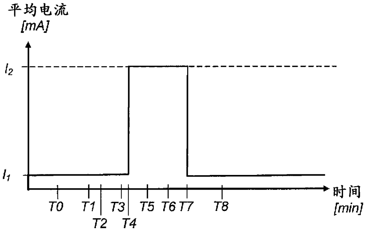
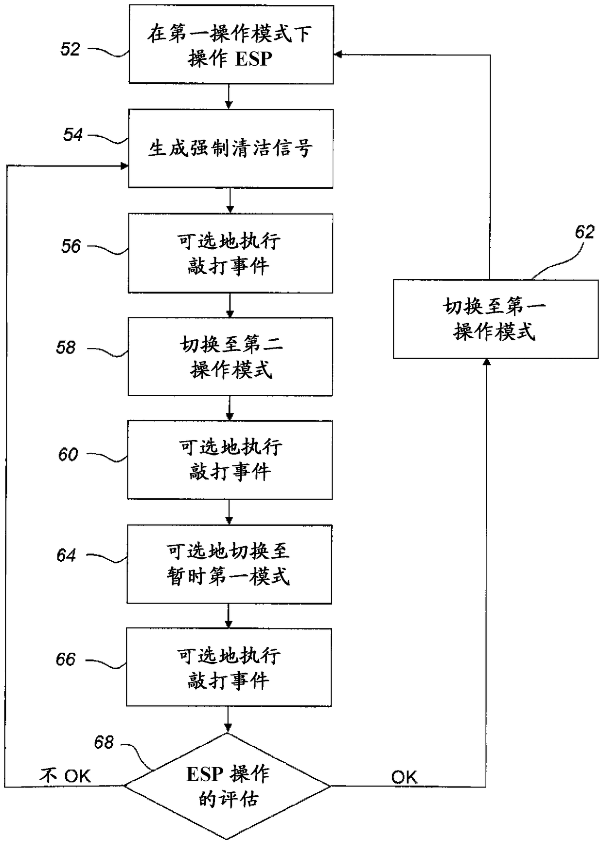
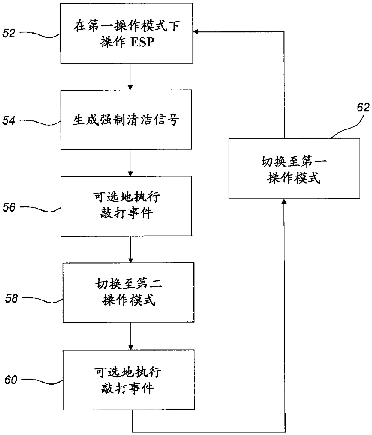
A method of cleaning at least one collecting electrode of an electrostatic precipitator comprises applying, in a first mode of operation, a first average current between at least one discharge electrode and at least one collecting electrode, and switching from the first mode of operation to a second mode of operation in which a second average current is applied between the at least one discharge electrode and the at least one collecting electrode, the second average current being a factor of at least 3 higher than the first average current, to achieve a forced cleaning of the at least one collecting electrode.

Description

technical field [0001] The invention relates to a method of cleaning at least one collector electrode of an electrostatic precipitator operative to remove dust particles from a process gas and comprising at least one discharge electrode and at least one collector electrode. [0002] The invention also relates to a device operative for cleaning at least one collecting electrode of an electrostatic precipitator. Background technique [0003] In the combustion of fuels (such as coal, oil, peat, waste, etc.) in combustion plants (such as power plants), hot process gases are produced which contain, among other components, dust particles, sometimes called fly ash. Ash. Dust particles are usually removed from the process gas by means of electrostatic precipitators (also known as ESPs, eg of the type shown in EP2078563). [0004] One problem associated with ESP is the so-called back-corona effect, i.e. the high resistivity of the layer of already collected dust particles on the co...

Claims


Application Information

Patent Timeline
Patent Type & Authority Applications(China)
IPC IPC(8): B03C3/68B03C3/74
CPCB03C3/41B03C3/45B03C3/66B03C3/74B03C2201/24B03C3/763B03C3/765
Inventor A.贝克
Owner GENERAL ELECTRIC TECH GMBH
Why Eureka
Try Eureka