
Lifting system, method for electrical testing, vibration damper, and machine assembly

a technology of vibration damper and lifting system, which is applied in the direction of individual semiconductor device testing, generator/motor, instruments, etc., can solve the problems of installation vibration, disadvantageous coupling of such vibrations into a foundation, and often occurring vibrations, and achieve simple and robust control of vibration damper

Active Publication Date: 2019-07-16
SIEMENS AG
View PDF17 Cites 1 Cited by
  • Summary
  • Abstract
  • Description
  • Claims
  • Application Information

AI Technical Summary

Benefits of technology

The patent discusses a way to prevent vchniations caused by electric motors. It suggests using a machine model to predict how the motor will behave at different frequencies. This information is then used to control the vibration dampers, which can be as simple as adjusting the motor's angle. The main benefit is that this method allows for easy and effective control of the vibration dampers, even at a high level of balancing and homogeneity.

Problems solved by technology

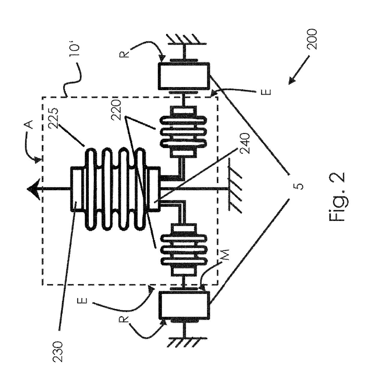
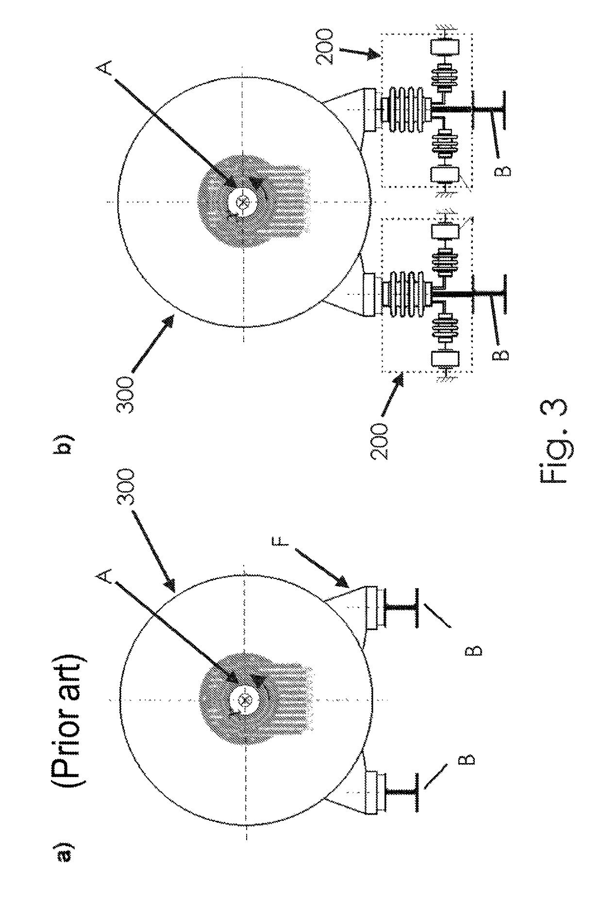
For example, during the operation of machines (e.g., large electric motors), vibrations often arise that are excited by imbalances or that are magnetically excited by a rotating magnetic flux between rotor and stator.
It is disadvantageously possible for such vibrations to be coupled into a foundation (e.g., to cause surrounding installations to vibrate).
Aside from comfort problems (e.g., noise and human vibration), this vibration often leads to damage as a result of fatigue failure.
However, a high level of balancing quality and a high level of homogeneity of the magnet guidance may be implemented only to a limited extent, or only at very great expense.

Method used


Image

  • Lifting system, method for electrical testing, vibration damper, and machine assembly
  • Lifting system, method for electrical testing, vibration damper, and machine assembly
  • Lifting system, method for electrical testing, vibration damper, and machine assembly

Examples


Embodiment Construction

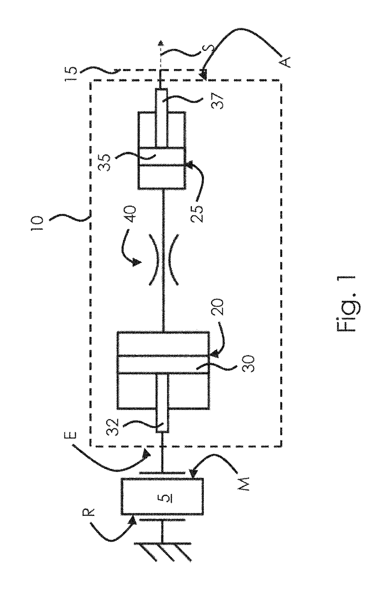
[0051]The lifting system according to an embodiment illustrated in FIG. 1 includes a piezo actuator 5 that is configured for effecting an actuation stroke in an actuation direction S. For this purpose, the piezo actuator 5 is fixedly clamped at one side R. From that side R, the piezo actuator 5 extends in the actuation direction S with an electrically manipulable length dimension in the longitudinal direction. The piezo actuator 5 has, averted from its clamped side R, a free end M that is spaced apart to a variable extent in the longitudinal direction from the clamped side R. The free end M of the piezo actuator 5 is attached to an input side E of a hydraulic stroke multiplier 10.

[0052]The stroke multiplier 10 has an output side A that is attached to a support (e.g., lifting table panel 15). The lifting table panel 15 is indicated in FIG. 1 as a dashed vertical line.

[0053]The hydraulic stroke multiplier 10 includes an input-side piston chamber 20 and, hydraulically coupled thereto, ...


PUM


Abstract

The invention relates to a lifting system, comprising a piezoelectric actuator (5), a support (15), and a hydraulic stroke multiplier (10) having an input and an output side, wherein the input side of the hydraulic stroke multiplier is connected to the piezoelectric actuator (5), and the output side of the hydraulic stroke multiplier is connected to the support (15). In the method for electrically testing an electronic component, the component is placed on the support of such a lifting system and is lifted for positioning relative to a test contact. The vibration damper comprises such a lifting system. The machine assembly has a machine and such a vibration damper.

Description

CROSS-REFERENCE TO RELATED APPLICATIONS[0001]This application is the National Stage of International Application No. PCT / EP2014 / 070803, filed Sep. 29, 2014 that claims the benefit of German Patent Application No. DE 10 2013 219632.6, filed Sep. 27, 2013 and German Patent Application No. DE 10 2014 219604.3, filed Sep. 26, 2014. The entire contents of these documents are hereby incorporated herein by reference.BACKGROUND[0002]The present embodiments relate to a lifting system, to a method for electrical testing, to a vibration damper and to a machine assembly.[0003]For the electrical testing of electronic components (e.g., for the testing of LEDs), lifting systems are commonly required that lift the electronic component on a support. During the lifting of the electronic component, a contact is placed against the electronic component such that the electronic component may have a measurement voltage applied to it for the electrical testing.[0004]In lifting systems for this purpose, act...

Claims


Application Information

Patent Timeline
Patent Type & Authority Patents(United States)
IPC IPC(8): H02N2/04F16F15/00G01R31/28G01R31/26F16F15/027H02K5/24
CPCH02N2/043F16F15/005F16F15/007G01R31/2635G01R31/286H02K5/24F16F15/027G01R31/2881
Inventor BACHMAIER, GEORGEBELSBERGER, GERITGERHARD, DETLEFGODECKE, ANDREASZOLS, WOLFGANG
Owner SIEMENS AG
Learn More