Apparatus and method for coding signal in a communication system

a communication system and signal technology, applied in the field of communication systems, can solve problems such as gain compensation of a restored highband signal, error of gain-compensated signal, and increase user demand for high quality services

Active Publication Date: 2011-11-17
ELECTRONICS & TELECOMM RES INST
View PDF2 Cites 15 Cited by
  • Summary
  • Abstract
  • Description
  • Claims
  • Application Information

AI Technical Summary

Problems solved by technology

Further, many methods have been introduced to transmit data at a high transmit rate with various QoSs through limited resources in such a communication system.
It causes the increment of user demands for high quality services through highband voice and audio such as a music streaming service.
However, there is a problem in restoration of the encoded voice and audio signal using the gain information encoded at the BWE layer when the encoder divides a wideband and a super wideband to multiple subbands and independently performs the encoding operation for providing the high quality voice and audio service.
In other words, there is a problem in gain compensation of a restored highband signal using gain information encoded at a BWE layer after the receiver restores the highband signal using a restored lowband signal.
When the receiver restores the highband signal using the restored lowband signal and uses the gain information encoded at the BWE layer for gain compensation of the restored highband signal, a gain-compensated signal has an error because the encoded gain information does not indicate a real gain of each band, particularly, a real gain of a highband.
Such an error causes deteriorating audio quality.
That is, such a gain mismatch problem is generated at a band boundary of the divided subbands by performing the gain compensation operation per each divided subband using the encoded gain information when the gain compensation operation is performed for restoring the encode signal.
The gain mismatch problem deteriorates the audio quality.

Method used


Image

  • Apparatus and method for coding signal in a communication system
  • Apparatus and method for coding signal in a communication system
  • Apparatus and method for coding signal in a communication system

Examples


Embodiment Construction

[0020]Exemplary embodiments of the present invention will be described below in more detail with reference to the accompanying drawings. The present invention may, however, be embodied in different forms and should not be constructed as limited to the embodiments set forth herein. Rather, these embodiments are provided so that this disclosure will be thorough and complete, and will fully convey the scope of the present invention to those skilled in the art.

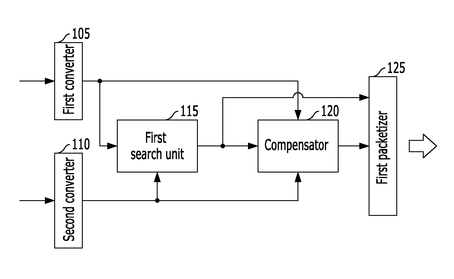
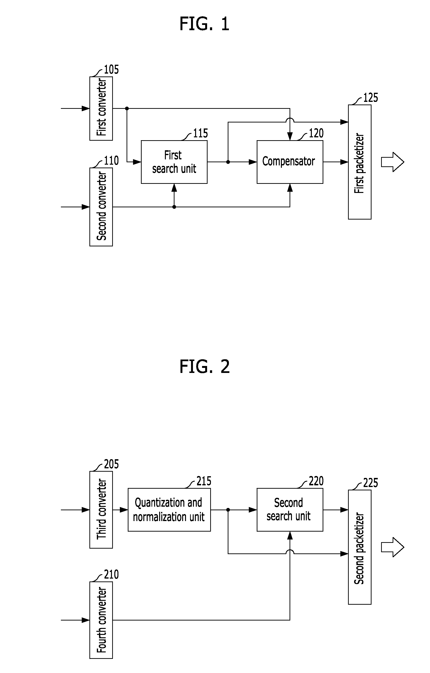
[0021]The present invention relate to an apparatus and method for encoding a signal in a communication system. Embodiments of the present invention relates to an apparatus and method for encoding a voice and audio signal by expanding a modified discrete cosine transform (MDCT) based CODEC to a wideband and a super-wideband in a communication system. In other words, in the embodiments of the present invention, a voice and audio signal is encoded by extending a related CODEC to a wideband and a super wideband in order to provide a h...


PUM


Abstract

Provided is an apparatus and method for encoding a voice and audio signal by expanding a modified discrete cosine transform (MDCT) based CODEC to a wideband and a super-wideband in a communication system. The apparatus for encoding a signal in a communication system, includes a converter configured to convert a time domain signal corresponding to a service to be provided to users to a frequency domain signal, a quantization and normalization unit configured to calculate and quantize gain of each subband in the converted frequency domain signal and normalize a frequency coefficient of the each subband, a search unit configured to search patch information of each subband in the converted frequency domain signal using the normalized frequency coefficient, and a packetizer configured to packetize the quantized gain and the searched patch information and encode gain information of each subband in the frequency domain signal.

Description

CROSS-REFERENCES TO RELATED APPLICATIONS[0001]The present application claims priority of Korean Patent Application Nos. 10-2010-0044591 and 10-2010-0091025, filed on May 12, 2010, and Sep. 16, 2010, respectively, which are incorporated herein by reference in their entirety.BACKGROUND OF THE INVENTION[0002]1. Field of the Invention[0003]Exemplary embodiments of the present invention relate to a communication system; and, more particularly, to an apparatus and method for encoding a voice and audio signal by expanding a modified discrete cosine transform (MDCT) based CODEC to a wideband and a super-wideband in a communication system.[0004]2. Description of Related Art[0005]There have many studies actively made to provide services with various Quality of Services (QoS) at a high transmit rate in a communication system. Further, many methods have been introduced to transmit data at a high transmit rate with various QoSs through limited resources in such a communication system. Due to the...

Claims


Application Information

Patent Timeline
Patent Type & Authority Applications(United States)
IPC IPC(8): H04L27/00
CPCG10L19/0208G10L21/038G10L19/24G10L19/0212
Inventor LEE, MI-SUKKIM, HONG-KOOKLEE, YOUNG-HAN
Owner ELECTRONICS & TELECOMM RES INST
Why Eureka
Try Eureka