Techniques for detecting optical faults in passive optical networks

a technology of optical fault detection and passive optical network, applied in the field of passive optical network, can solve the problems of long service interruption time and network topology chang

Active Publication Date: 2011-11-17
AVAGO TECH INT SALES PTE LTD
View PDF4 Cites 52 Cited by
  • Summary
  • Abstract
  • Description
  • Claims
  • Application Information

AI Technical Summary

Benefits of technology

[0018]FIG. 2 is a schematic diag

Problems solved by technology

Performing such a process when establishing the network is an error prone approach as the “range” between the OLTs 210 and the terminal units (i.e., ONUs 240) may change over time and therefore there may be different RTT times and optical power levels for signals transmission power.
Per

Method used


Image

  • Techniques for detecting optical faults in passive optical networks
  • Techniques for detecting optical faults in passive optical networks
  • Techniques for detecting optical faults in passive optical networks

Examples


Embodiment Construction

[0027]It is important to note that the embodiments disclosed are only examples of the many advantageous uses of the innovative teachings herein. In general, statements made in the specification of the present disclosure do not necessarily limit any of the various claimed inventions. Moreover, some statements may apply to some inventive features but not to others. In general, unless otherwise indicated, singular elements may be in plural and vice versa with no loss of generality. In the drawings, like numerals refer to like parts through several views.

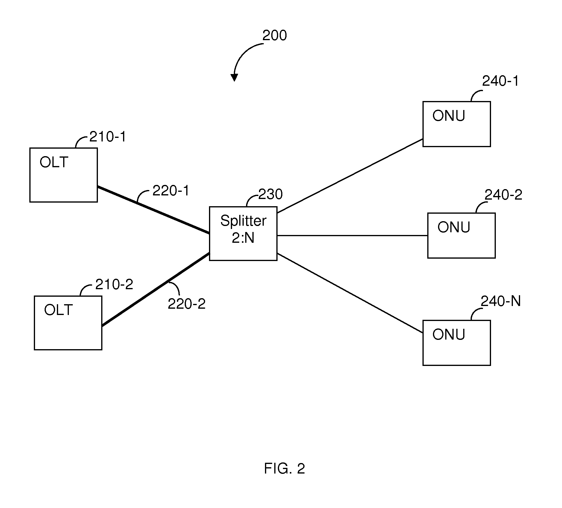
[0028]FIG. 3 shows an exemplary block diagram of a duplex PON 300 constructed in accordance with an embodiment of the invention. The PON 300 includes two OLTs 310-1 and 310-2 respectively coupled to a splitter 321-1 or 321-2 via optical links (e.g., optical fibers) 330-1 and 330-2. The splitters 321-1 and 321-2 are coupled to a number of N ONUs 340-1 to 340-N (collectively ONU 340) where a single optical link connects the splitter and e...


PUM


Abstract

A method for detecting faults and their locations in an optical path between an optical line terminal (OLT) of and optical network units (ONUs) of a passive optical network (PON). The method comprises forming a maintenance optical link through the PON between the OLT and a collocated ONU, the OLT and its collocated ONU are each connected to an optical splitter; sending a ranging request from the OLT to the collocated ONU; in response to the ranging request, receiving, over the maintenance optical line, a ranging burst signal including at least a fault analysis detection pattern (FADP); and analyzing the FADP in the received signal by auto-correlating the FADP signal with an expected FADP signal, an uncorrelated event measured through the auto-correlation is indicative of a fault in the optical path of the PON and occurrence times of such events are indicative of the fault's location in the optical path.

Description

CROSS REFERENCE TO RELATED APPLICATIONS[0001]This application is a continuation-in-part of U.S. patent application Ser. No. 12 / 648,885 filed on Dec. 29, 2009. The 12 / 648,885 application claims the benefit of U.S. Provisional Application No. 61 / 141,489 filed on Dec. 30, 2008, the contents of which are herein incorporated by reference.TECHNICAL FIELD[0002]The present invention relates generally to passive optical networks (PONs), and more particularly to protection of such networks.BACKGROUND OF THE INVENTION[0003]A passive optical network (PON) comprises an optical line terminal (OLT) connected to multiple optical network units (ONUs) in a point-to-multi-point network. New standards have been developed to define different types of PONs, each of which serves a different purpose. For example, the various PON types known in the related art include a Broadband PON (BPON), an Ethernet PON (EPON), a Gigabit PON (GPON), XGPON, and others.[0004]An exemplary diagram of a typical PON 100 is sc...

Claims


Application Information

Patent Timeline
IPC IPC(8): H04B10/08
CPCH04B10/0771H04J3/0682H04J3/14H04J3/1694H04Q2011/0083H04Q11/0067H04Q2011/0015H04Q2011/0035H04Q2011/0081H04J2203/006
Inventor DVIR, AMIADELMOALEM, ELI
Owner AVAGO TECH INT SALES PTE LTD
Why Eureka
Try Eureka