Dispensing closure having a flow conduit with key-hole shape

a flow conduit and dispensing closure technology, applied in the direction of closures using stoppers, caps, liquid handling, etc., can solve the problems of difficult manufacturing, more expensive than traditional one-piece dispensing closures, and a messy appearan

Active Publication Date: 2011-11-24
WESTROCK SLATERSVILLE
View PDF4 Cites 11 Cited by
  • Summary
  • Abstract
  • Description
  • Claims
  • Application Information

AI Technical Summary

Problems solved by technology

Past dispensing closures tended to leak product onto the top deck of the closure after dispensing, creating a messy appearance and often requiring cleaning to reseal the closure.
While these silicone valves have been widely accepted by both the manufacturers and the consumers, they are somewhat more difficult to manufacture, as they require several inter-fitting parts, and thus they tend to be more expensive than traditional one-piece dispensing closures.
Another perceived drawback to the silicone valve closure is that they are constructed out of two different types of plastic and thus, from a recycling standpoint, they are more difficult to recycle because the silicone valve must be separated from the plastic closure body

Method used


Image

  • Dispensing closure having a flow conduit with key-hole shape
  • Dispensing closure having a flow conduit with key-hole shape
  • Dispensing closure having a flow conduit with key-hole shape

Examples


Embodiment Construction

Brief Description of the Drawings

[0010]The novel features which are characteristic of the dispensing closure are set forth in the appended claims. However, the dispensing closure, together with further embodiments and attendant advantages, will be best understood by reference to the following detailed description taken in connection with the accompanying drawing Figures.

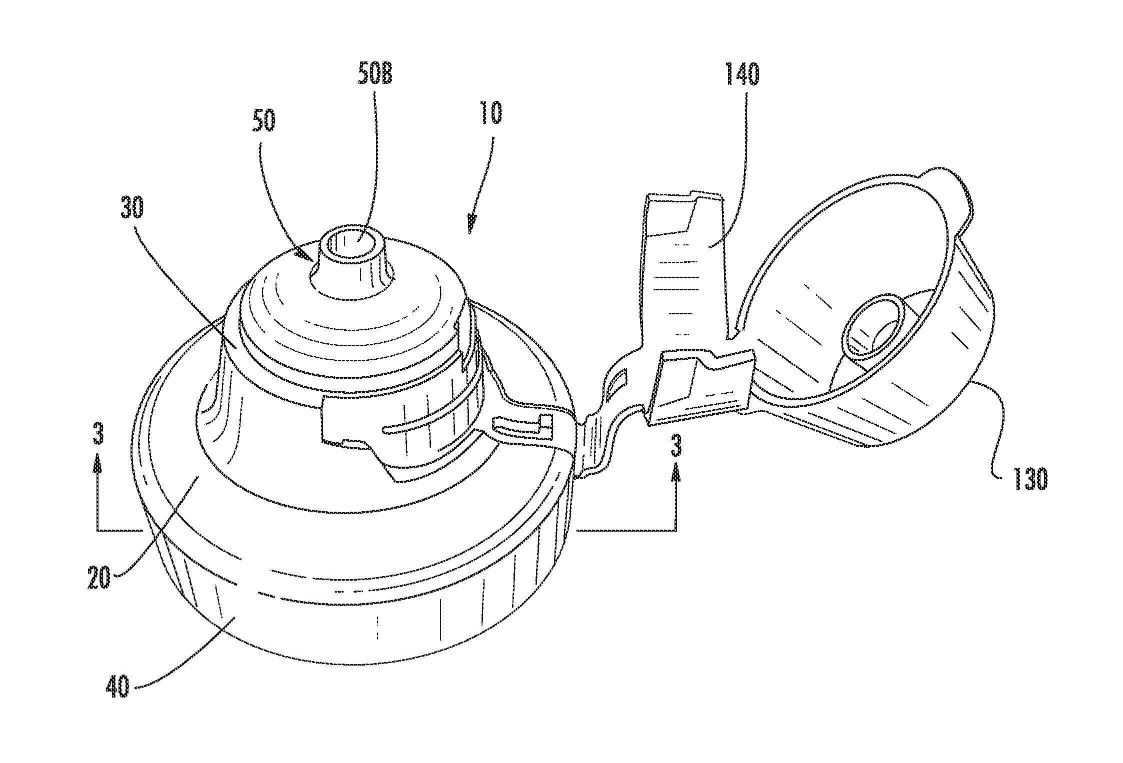
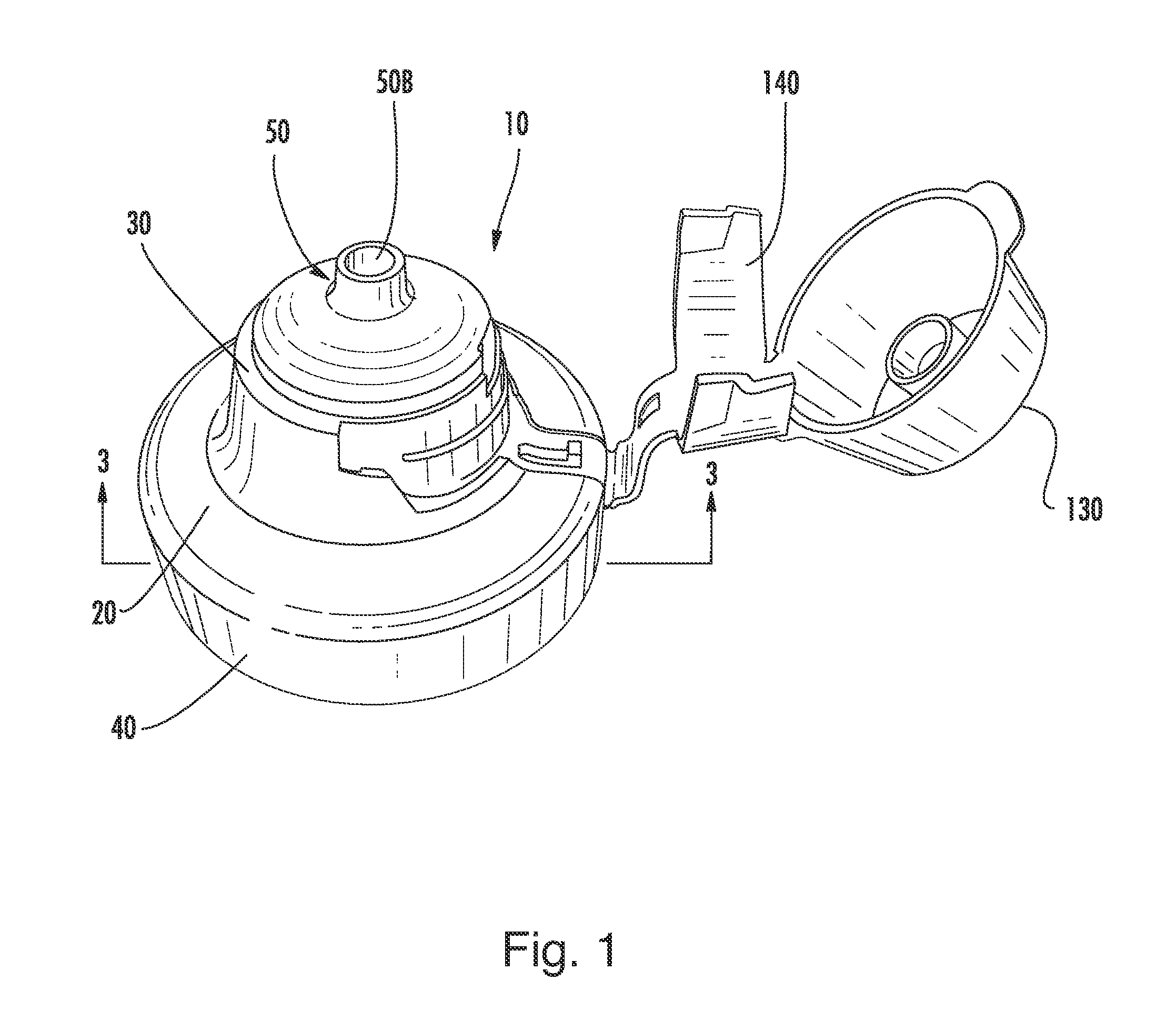
[0011]FIG. 1 is a perspective view of the dispensing closure constructed in accordance with the teachings of the present invention;

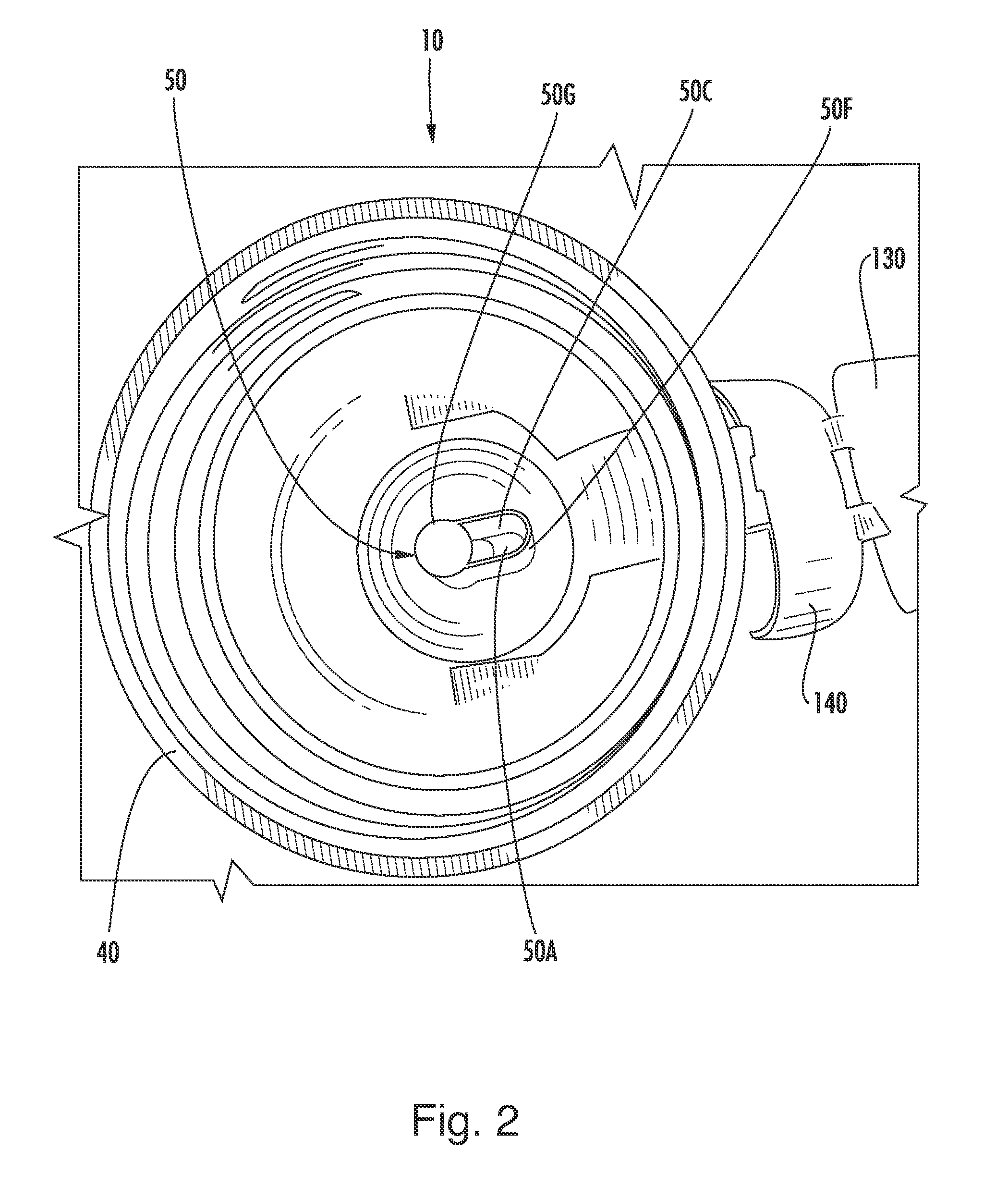
[0012]FIG. 2 is a bottom view thereof;

[0013]FIG. 3 is a cross-sectional view of thereof as taken along line 3-3 of FIG. 1;

[0014]FIG. 4 is a diagrammatical view thereof;

[0015]FIG. 5 is a bottom view of another embodiment having a double key-hole shaped flow conduit;

[0016]FIG. 6 is a cross-sectional view of FIG. 5;

[0017]FIG. 7 is a diagrammatical view of invention of FIG. 5;

[0018]FIG. 8 is a cross-sectional view of another embodiment having a key-hole flap and a partition wall;

[0019]FIG. 9 ...


PUM


Abstract

A dispensing closure has a key-hole shaped flow conduit that provides a sufficient flow restriction to prevent unwanted spurting of the product. The dispensing closure includes a closure body with an upper and lower deck, inner and outer skirt, and a flow conduit extending through the upper deck. The flow conduit includes including two or more vertically oriented walls and a bottom wall. The vertically oriented walls define a fluid trapping area and a partition wall depending downwardly from said upper deck. The bottom wall configured and arranged to be positioned along a horizontal axis. The flow conduit includes one entrance orifice having one entrance axis and an exit orifice having an exit axis. The entrance axis is stepped or offset from the exit axis whereby the flow conduit provides a non-linear flow path of product from an interior of the closure to an exterior of the closure.

Description

CROSS REFERENCE TO RELATED APPLICATIONS[0001]This continuation-in-part application is related to and claims priority from earlier filed, U.S. Provisional Pat. Appl. No. 61 / 347,708 filed May 24, 2010, U.S. Non-Provisional patent application Ser. No. 12 / 616,346 filed Nov. 11, 2009, U.S. Non-Provisional patent application Ser. No. 11,849,979 filed Sep. 4, 2007, U.S. Provisional Patent Application No. 60 / 893,883 filed Mar. 8, 2007 and U.S. Provisional Patent Application No. 60 / 824,322 filed Sep. 1, 2006, all of which are incorporated herein by reference.BACKGROUND OF THE INVENTION[0002]The present invention relates to container closures, and more particularly to squeeze-type container dispensing closures.[0003]There are two major trends occurring in the design of dispensing containers and closures. The first trend is a focus on providing a “clean pour” during dispensing of the product. Many food products, such as mustard and ketchup, have a high viscosity and require the user to tip the...

Claims


Application Information

Patent Timeline
IPC IPC(8): B65D47/00B65D37/00
CPCB65D2547/063B65D47/06
Inventor BRANNON, PATRICK J.SKILLIN, CLIFFORD W.ROMANOV, SERGEY
Owner WESTROCK SLATERSVILLE
Why Eureka
Try Eureka