RFID security and mobility architecture

a technology of rfid and mobility architecture, applied in the field of secure communications, can solve the problems of unsecured communication within the rfid system (e.g., between interrogators and tags), and the tags are vulnerable to unauthorized reading, and achieve the effect of less secure environmen

Inactive Publication Date: 2011-12-01
SAVI TECH INC
View PDF3 Cites 162 Cited by
  • Summary
  • Abstract
  • Description
  • Claims
  • Application Information

AI Technical Summary

Benefits of technology

[0039]AES-CBC—AES with Cipher Block Chaining;
[0040]The Advanced Encryption Standard is a symmetric-key encryption standard adopted by the U.S. government. AES was announced by the National Institute of Standards and Technology (NIST) as U.S. FIPS PUB 197 (FIPS 197), a publication that can be found at http://csrc.nist.gov/publications/fips/fips197/fips-197.pdf.
[0041]Security protocols according to some embodiments of the present invention include two components—the wireless RFID security infrastructure and the wired security infrastructure. The wired security infrastructure provides for a secure key distribution and support for the mobility of tags 110 between different RF security domains (which is discussed further below). As described herein, wireless RFID security infrastructure can be extensions of an existing protocol such as the ISO 18000-7 (Mode 1) protocols or the Mode 2 protocols. As such, in some embodiments at least some of devices 110 can support both wireless protocols and wired protocol, including internet protocol support.
[0042]In some embodiments, the wireless protocols can provide confidentiality by encrypting frames to protect message integrity; protect data integrity; provide replay protection with replay counters as part of the wireless frame; and protect against denial of service. Further, in some embodiments, mutual authentication of communicating devices 110 can occur. Secure key distribution can also be i...

Problems solved by technology

However, communications within the RFID system (e.g., between interrogator and tags) have...

Method used


Image

  • RFID security and mobility architecture
  • RFID security and mobility architecture
  • RFID security and mobility architecture

Examples


Embodiment Construction

[0029]The figures and the following description relate to some embodiments by way of illustration only. It should be noted that from the following discussion, alternative embodiments of the structures and methods disclosed herein will be readily recognized as viable alternatives that may be employed without departing from the principles of the embodiments described herein.

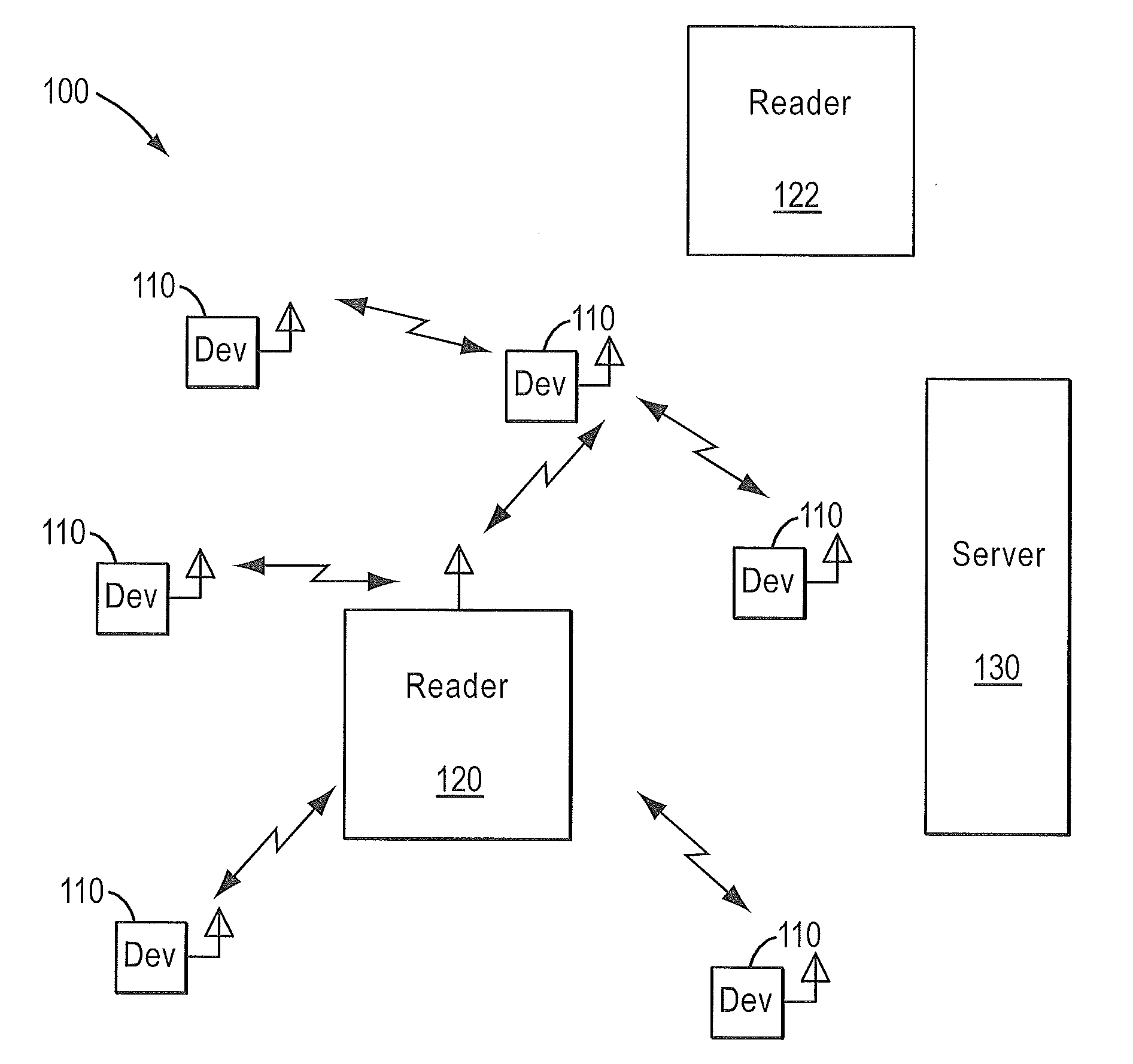
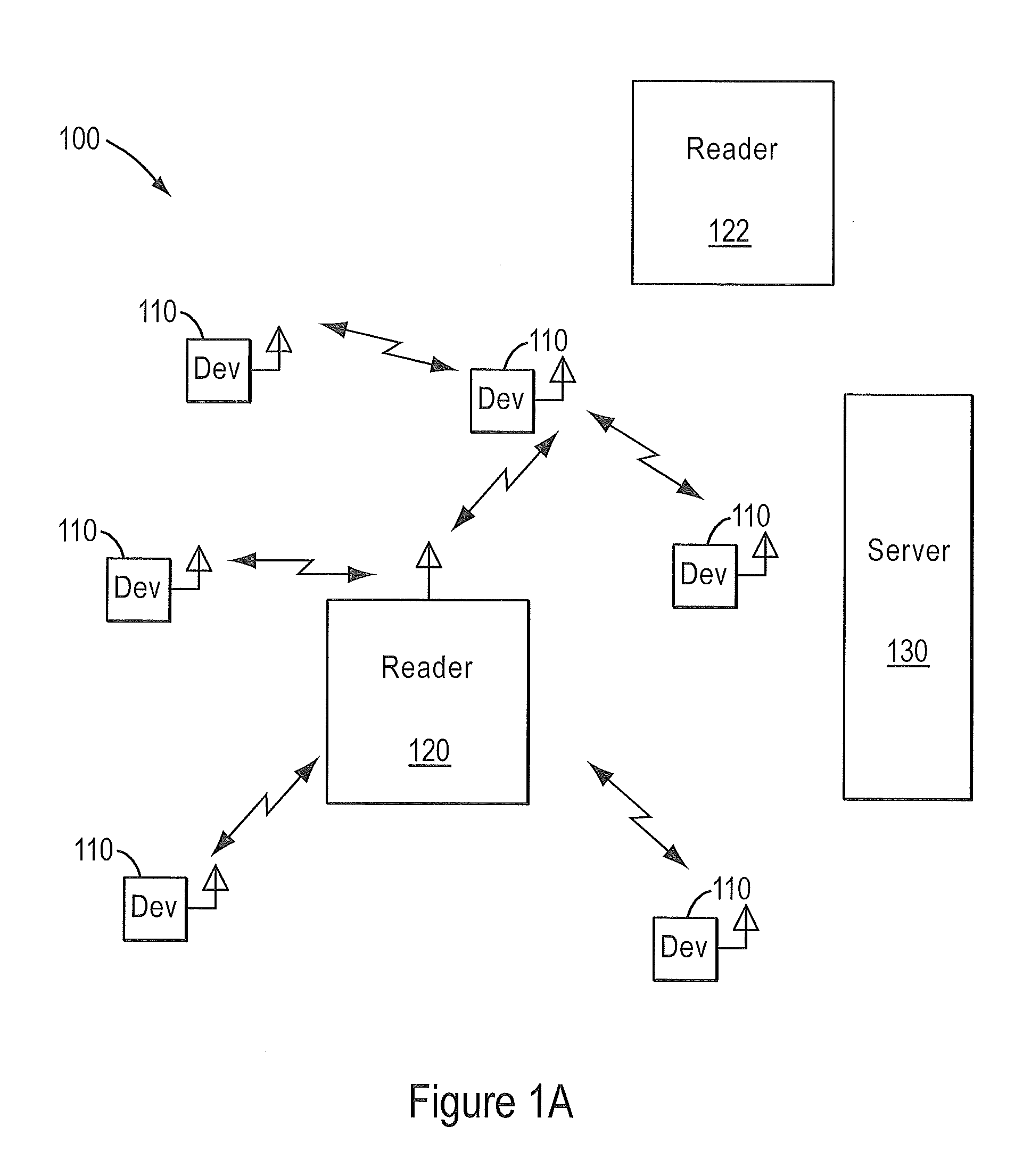
[0030]FIG. 1A illustrates a typical radio-frequency identification (RFID) domain 100. Devices 110 are typically attached to assets that are moved into and out of an area. Reader 120 and devices 110 communicate data. In some embodiments, reader 120 can be one of many mobile or fixed interrogators. Further, in some embodiments reader 120 may be part of an integrated RFID domain and may be controlled by a central server 130 in domain 100. Server 130 may communicate with multiple other readers 122 at domain 100. Domain 100 is an example of a security domain that may exists at a terminal or shipping point.
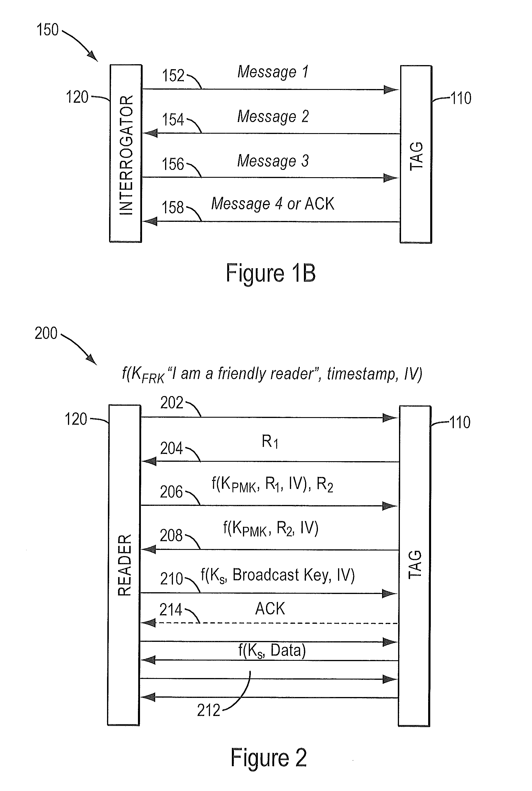
[0031]Readers ...


PUM


Abstract

A method of communication between RFID devices that includes mutually authenticating the RFID devices is disclosed. Once mutual authentication is completed, one or more encrypted messages based on the encryption scheme can be exchanged between the RFID devices.

Description

RELATED APPLICATIONS[0001]The present application claims priority to U.S. Provisional Application No. 61 / 348,986, filed on May 27, 2010, U.S. Provisional Application No. 61 / 366,200, filed on Jul. 21, 2010, and U.S. Provisional Application No. 61 / 380,986, filed on Sep. 8, 2010, each of which is herein incorporated by reference in its entirety.BACKGROUND[0002]1. Field of the Invention[0003]Embodiments of the present invention are directed towards secured communications in RFID environments.[0004]2. Description of Related Art[0005]Low-power wireless devices such as, for example, radio frequency (RF) tags have been in use for some time. Radio-frequency identification (RFID) systems typically include interrogators or readers that communicate with tags. Tags are typically attached to an article such as a shipping container or a package that is being shipped. The interrogator, then, can inventory the articles that are within its range.[0006]Generally, an RFID tag system will include a numb...

Claims


Application Information

Patent Timeline
IPC IPC(8): H04Q5/22
CPCH04Q2213/095G08B13/2462H04L2209/805H04L9/3273G08B13/2482
Inventor BAJIC, ZELJKOCARGONJA, NIKOLAHO, JOSEPH S.M.SCHNELL, RICHARD
Owner SAVI TECH INC
Why Eureka
Try Eureka