Binding device

a technology of binding device and hose, which is applied in the direction of hose connection, manufacturing tools, other domestic articles, etc., can solve the problems of unclear overall configuration details, and achieve the effect of improving the retention strength of the binding device, easy and inexpensive production

Inactive Publication Date: 2011-12-15
NEWFREY
View PDF12 Cites 8 Cited by
  • Summary
  • Abstract
  • Description
  • Claims
  • Application Information

AI Technical Summary

Benefits of technology

[0014]In the present invention, a binding device can be provided in which the retention strength of the binding device is improved, especially in the extraction direction. Also, this binding device can be easily and inexpensively made.

Problems solved by technology

However, how this binding device is made has not been disclosed, and the details of the overall configuration are not at all clear.

Method used


Image

  • Binding device
  • Binding device
  • Binding device

Examples


Embodiment Construction

[0023]The following is an explanation of the binding device in a preferred embodiment of the invention in the present application with reference to the appended drawings.

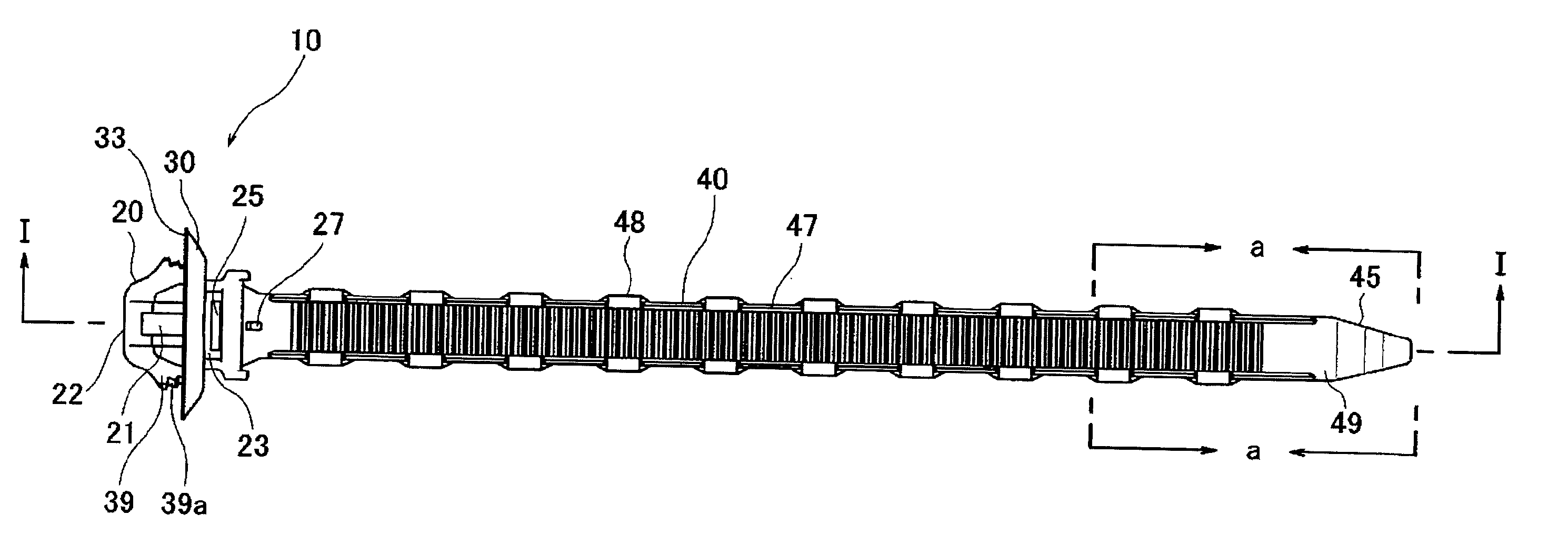
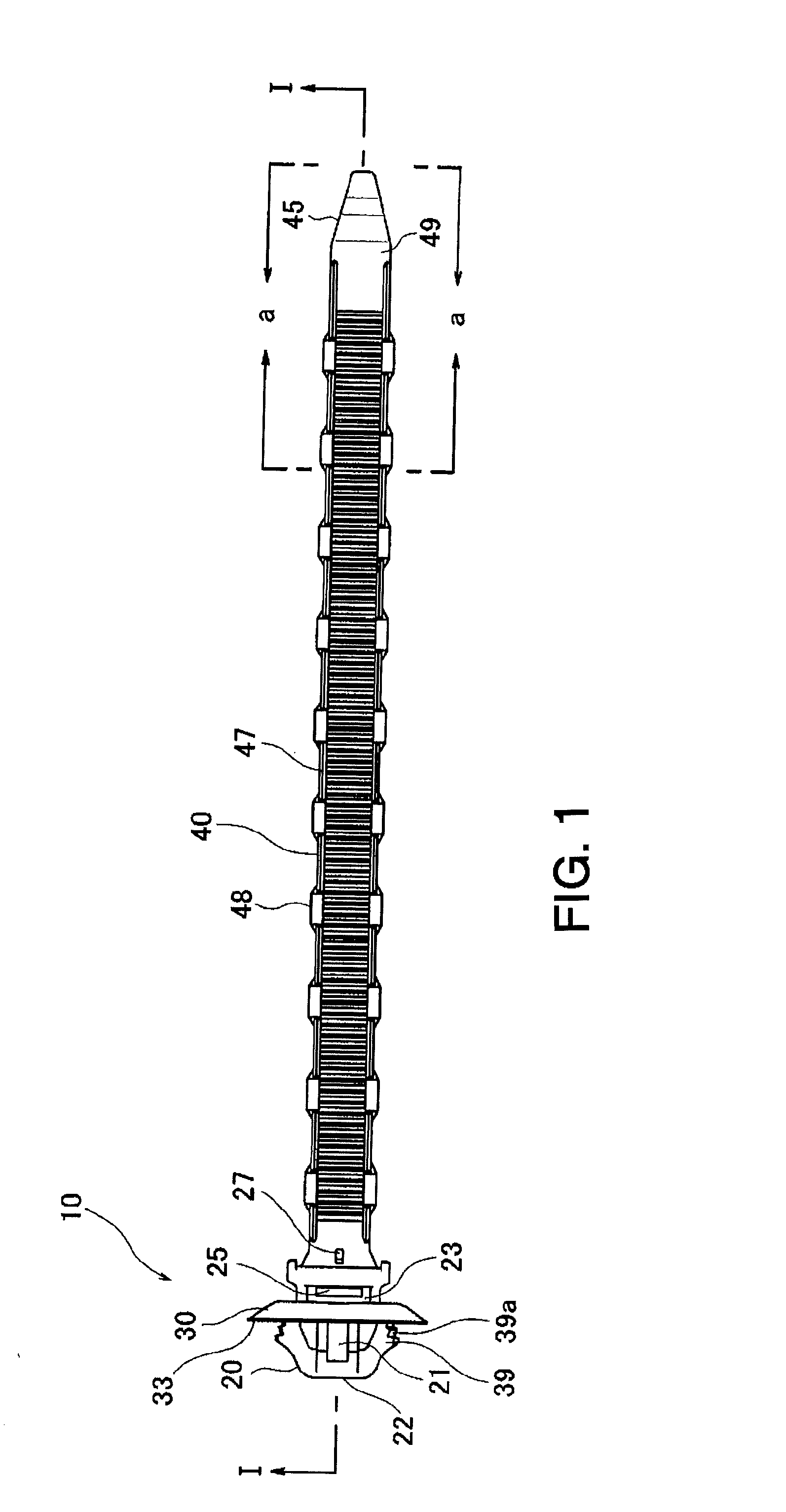
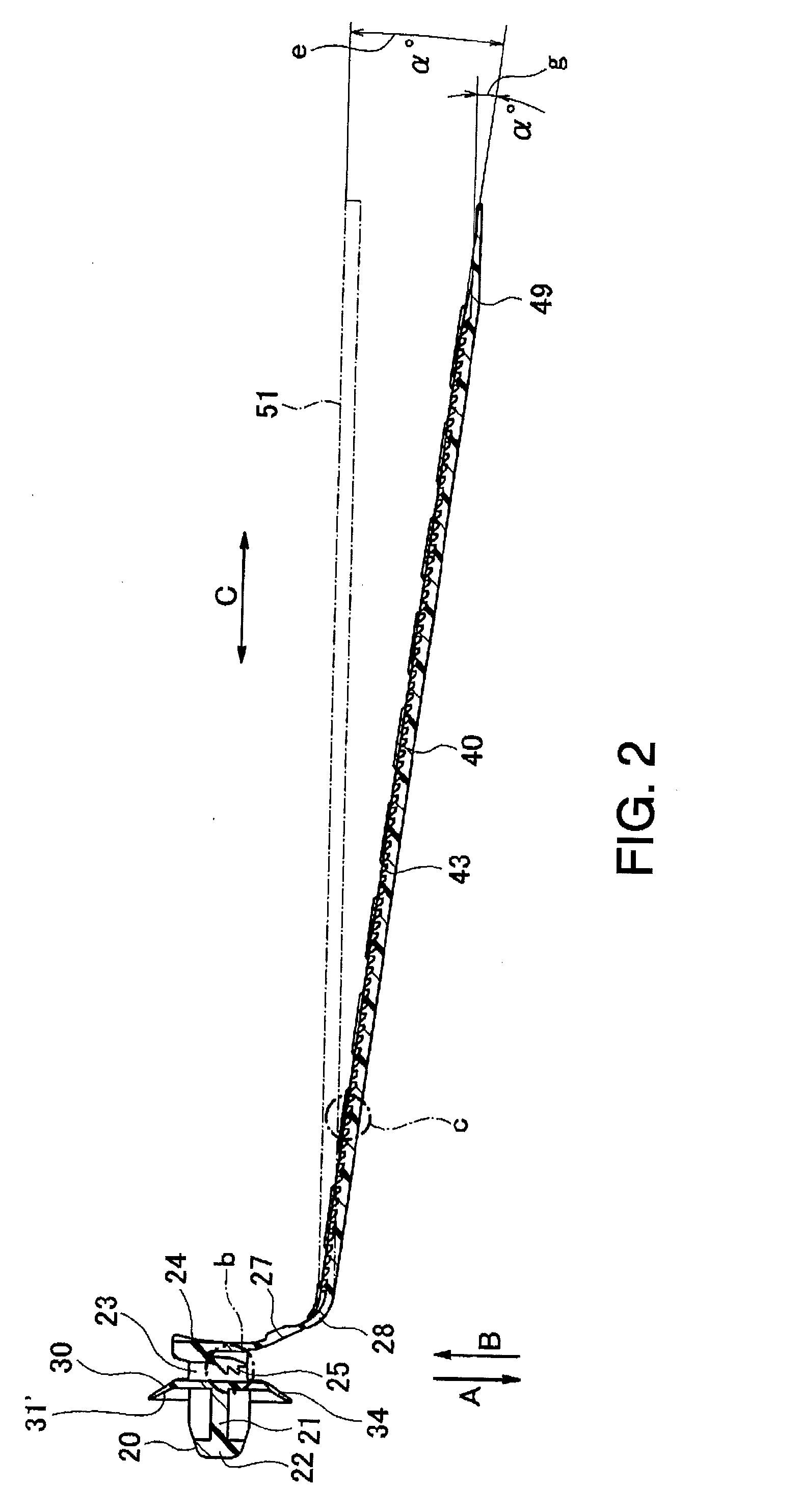
[0024]FIG. 1 is a top view of a binding device 10 according to the present invention, and FIG. 2 is a cross-sectional view from line I-I in FIG. 1. The binding device 10 primarily includes a belt-like band 40 having flexibility and a head portion buckle 20 disposed at one end in the lengthwise direction of the band.

[0025]The buckle 20 functions as a portion for securing the band 40, and also functions as a portion for securing the binding device 10 to a panel, etc. The configuration serving as the securing portion for a panel is similar to a general binding device. This is explained in greater detail in, for example, Japanese Published Patent Application No. 8-145021. Simply put, in order to secure a panel, the buckle 20 mainly includes a pair of engaging pieces 39 with flexibility connected to a support pillar 21 a...


PUM

PropertyMeasurementUnit
acute angleaaaaaaaaaa
flexibilityaaaaaaaaaa
acute angleaaaaaaaaaa

Abstract

This invention provides a method for the easy manufacture of a binding device in which resistance in the extraction direction is strengthened by applying an inclination to a movable clasp and ratchet teeth, and provides a binding device manufactured using this manufacturing method. The device includes a band-like body having flexibility and a head portion disposed on an end of the band-like body in the lengthwise direction. The other end of the band-like body in the lengthwise direction is inserted into a through-hole disposed in the head portion to form a loop for securing purposes. The band-like body is connected to the head portion via a curved portion, and an acute angle is formed centered on the curved portion in the direction orthogonal to the insertion direction, etc. of the band-like body into the through-hole.

Description

CROSS-REFERENCE TO RELATED APPLICATIONS[0001]This application claims priority from Japanese Patent Application No. 2010-136261, filed on Jun. 15, 2010, the disclosure of which is incorporated herein by reference.BACKGROUND OF THE INVENTION[0002]The present invention relates to a binding device and, more specifically, to a binding device able to secure an object by wrapping the band portion of the binding device into a loop.[0003]An example of this type of binding device has been disclosed in Patent Document 1, Japanese Published Unexamined Patent Application No. 09-188355. The binding device disclosed includes a slender tongue portion having flexibility and a head portion disposed on one end of the slender tongue portion. The other end of the slender tongue portion is inserted into a through-hole disposed in the head portion to form a loop of the desired size. This loop can secure a bound object such as slender cable or metal rod. In order to secure the loop, a movable clasp is disp...

Claims


Application Information

Patent Timeline
Patent Type & Authority Applications(United States)
IPC IPC(8): B65D63/10B29C45/00B65D63/00
CPCY10T24/14B65D63/1072
Inventor SANO, TAKAHIRO
Owner NEWFREY
Why Eureka
Try Eureka