Eureka AIR delivers breakthrough ideas for toughest innovation challenges, trusted by R&D personnel around the world.

Evaporator

Active Publication Date: 2011-12-15
MAHLE INT GMBH
View PDF7 Cites 32 Cited by
  • Summary
  • Abstract
  • Description
  • Claims
  • Application Information

AI Technical Summary

Benefits of technology

[0009]An object of the present invention is to solve the above problem and to provide an evaporator which can enhance cooling performance by equalizing the amounts of refrigerant flowing in heat exchange tubes of two tube groups, which are located farthest from a refrigerant inlet and a refrigerant outlet, which are juxtaposed in an air-passage direction and form a single path, and which are the same in terms of the flow direction of refrigerant within the heat exchange tubes.

Problems solved by technology

Although the evaporator disclosed in the publication can restrain an increase in passageway resistance at the final path, it has the following problem.
However, in this case, since the communication means projects from the heat exchange core portion in the lateral direction, a dead space is produced when the evaporator is installed.
Accordingly, the conventional evaporator is insufficient in terms of the effect of equalizing the amounts of refrigerant flowing in the heat exchange tubes of the two tube groups, which are juxtaposed in the air-passage direction and form a single path, and which are the same in terms of the flow direction of refrigerant within the heat exchange tubes.

Method used


Image

  • Evaporator
  • Evaporator
  • Evaporator

Examples


first embodiment

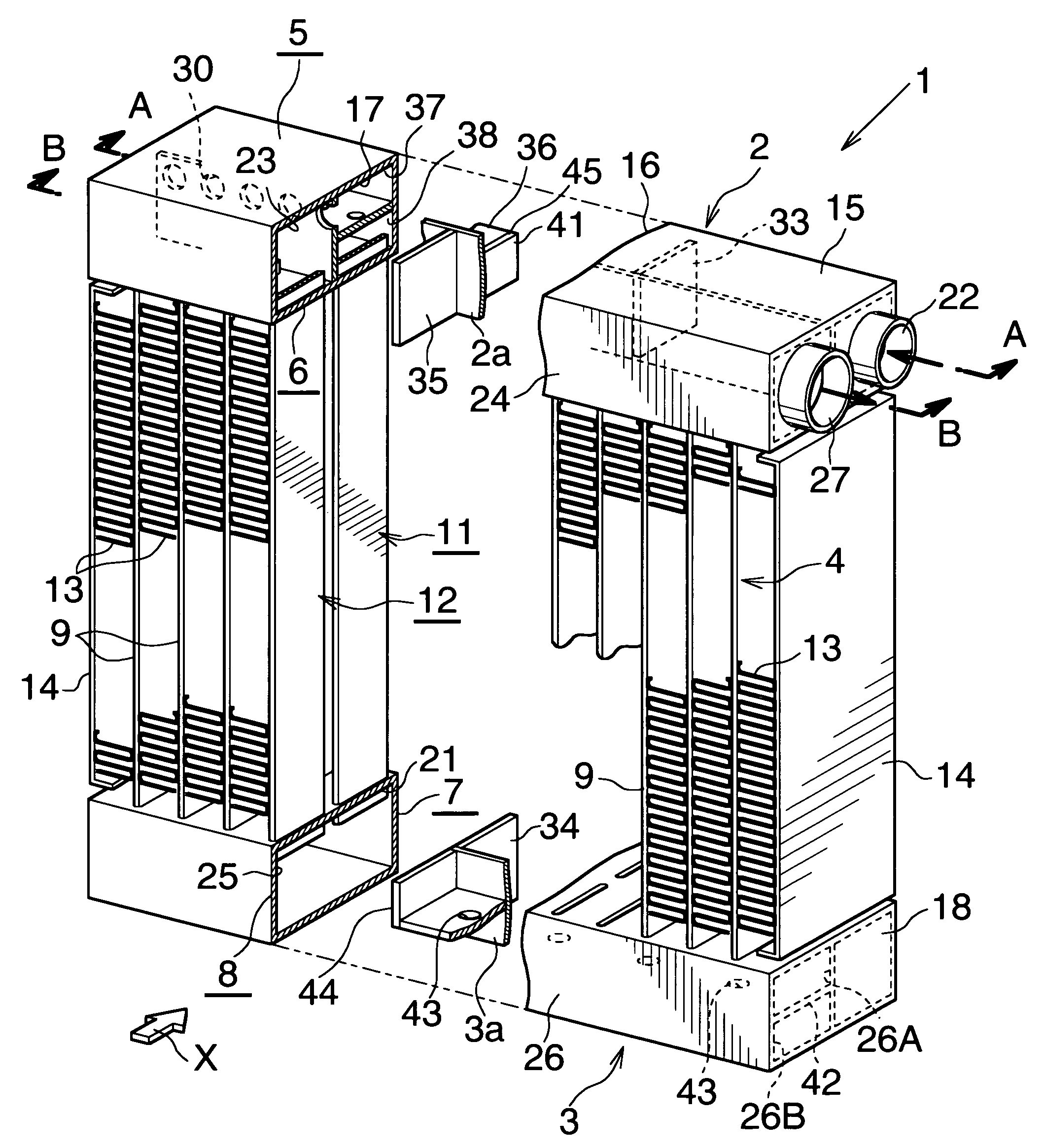
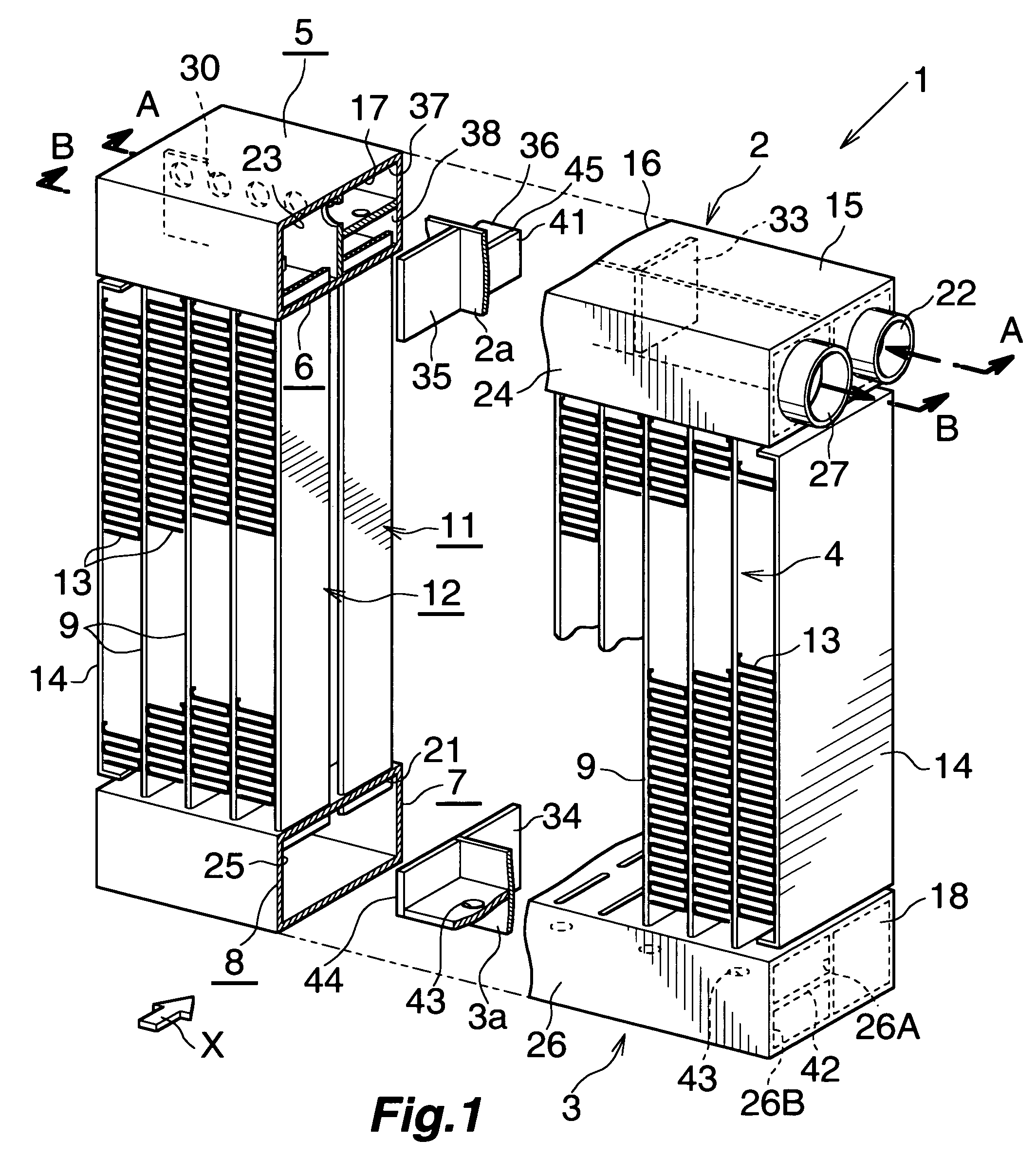
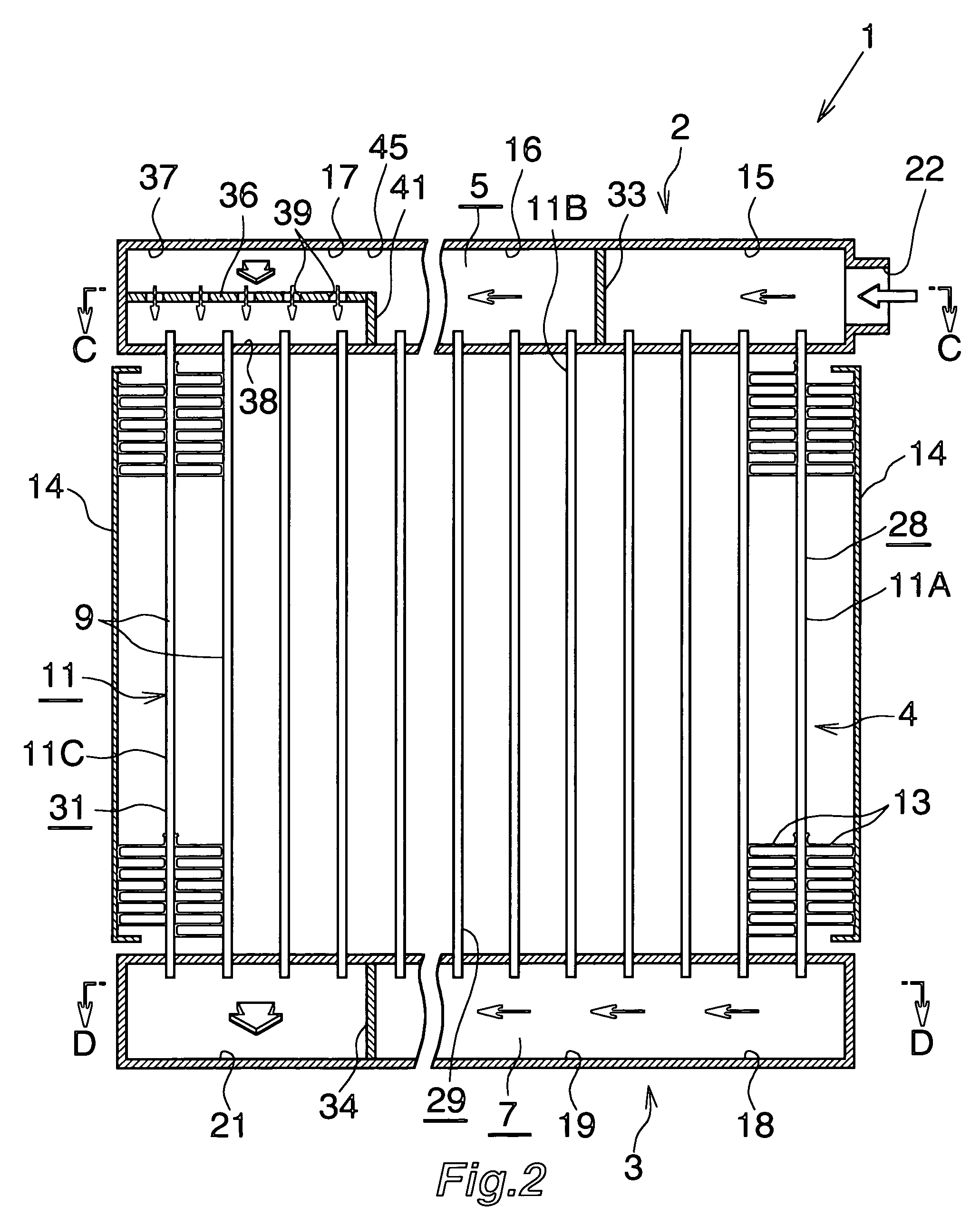
[0080]FIGS. 1 to 6 show a first embodiment of the present invention. FIG. 1 shows the overall configuration of an evaporator, and FIGS. 2 to 5 show the configurations of essential portions of the evaporator. FIG. 6 shows the flow of refrigerant within the evaporator of FIG. 1.

[0081]As shown in FIG. 1, an evaporator 1 includes a first header tank 2 and a second header tank 3 formed of aluminum and disposed apart from each other in the vertical direction; and a heat exchange core portion 4 provided between the two header tanks 2, 3.

[0082]The first header tank 2 includes a leeward header portion 5 located on the leeward side (front side), and a windward header portion 6 located on the windward side (rear side) and united with the leeward header portion 5. In the present embodiment, the leeward header portion 5 and the windward header portion 6 are provided by means of partitioning the first header tank 2 into front and rear portions by a partition portion 2a. The second header tank 3 i...

second embodiment

[0105]FIGS. 10 to 14 show a second embodiment of the present invention. FIGS. 10 to 13 show the configurations of essential portions of the evaporator, and FIG. 14 shows the flow of refrigerant within the evaporator of FIG. 10.

[0106]As shown in FIGS. 10 to 14, the leeward tube row 11 of the evaporator 50 includes four tube groups 11A, 11B, 11C, 11D, each of which is composed of a plurality of heat exchange tubes 9 and which are arranged from the right end toward the left end; and the windward tube row 12 includes three tube groups 12A, 12B, 12C (the number of which is one less than the number of the tube groups of the leeward tube row 11), each of which is composed of a plurality of heat exchange tubes 9 and which are arranged from the left end toward the right end.

[0107]The leeward upper and lower header portions 5, 7 have sections 51, 52, 53, 54 and sections 55, 56, 57, 58 respectively, the number of which is equal to the number of the tube groups 11A, 11B, 11C, 11D of the leeward...

third embodiment

[0122]FIGS. 15 to 17 show a third embodiment of the present invention. FIGS. 15 to 17 show the configurations of essential portions of the evaporator.

[0123]As shown in FIGS. 15 to 17, the resistance member for flow division 36 is not provided in the third section 17 (the leeward farthest section) of the leeward upper header portion 5 of an evaporator 90, and the flow cutoff member 41 is not provided between the second section 16 and the third section 17 of the leeward upper header portion 5. Accordingly, the second section 16 and the third section 17 communicate with each other over the entire cross section. Furthermore, a communication portion 91 provided in a portion of the partition portion 2a of the first header tank 2 located leftward of the partition wall 35 establishes communication between the third section 17 of the leeward upper header portion 5 and the fourth section 23 of the windward upper header portion 6.

[0124]The total channel sectional area of the refrigerant channe...


PUM


Abstract

A leeward tube row of an evaporator includes first to third tube groups, and a windward tube row thereof includes fourth and fifth tube groups. Within a third section of a leeward upper header portion with which heat exchange tubes of the third tube group communicate, a resistance member for flow division is provided so as to divide the interior of the third section into a first space which the heat exchange tubes face, and a second space which is separated from the first space and into which refrigerant flows. The resistance member for flow division has a plurality of refrigerant passage holes. The leeward upper header portion has a flow cutoff member for preventing flow of refrigerant into the first space of the third section. The third section of the leeward upper header portion communicates with the fourth section of the windward upper header portion via refrigerant communication passages.

Description

BACKGROUND OF THE INVENTION[0001]The present invention relates to an evaporator suitable for use in a car air conditioner, which is a refrigeration cycle to be mounted on an automobile, for example.[0002]In this specification and appended claims, the upper and lower sides of FIGS. 2, 3, 10, 11, 16, and 17 will be referred to as “upper” and “lower,” respectively.[0003]An evaporator of such a type has been proposed (see Japanese Patent Application Laid-Open (kokai) No. 2009-156532). The proposed evaporator comprises two tube rows juxtaposed in an air-passage direction, each tube row including a plurality of heat exchange tubes which extend vertically and are spaced from one another in a direction perpendicular to the air-passage direction; leeward upper and lower header portions provided on upper and lower sides of the leeward tube row; and windward upper and lower header portions provided on upper and lower sides of the windward tube row. The leeward tube row includes three or more t...

Claims


Application Information

Patent Timeline
IPC IPC(8): F28F9/02
CPCB60H1/00335F25B39/022F28D1/05391F28F9/0278F28F9/0204F28F9/026F28F9/0273F28D2021/0085
Inventor KAMOSHIDA, OSAMUHIGASHIYAMA, NAOHISATAKAGI, MOTOYUKIHIRAYAMA, TAKASHI
Owner MAHLE INT GMBH
Why Eureka
Eureka Blog
Learn More