Eureka AIR delivers breakthrough ideas for toughest innovation challenges, trusted by R&D personnel around the world.

Alternating type heat pump

Inactive Publication Date: 2013-06-06
JEON CHANG DUK
View PDF13 Cites 7 Cited by
  • Summary
  • Abstract
  • Description
  • Claims
  • Application Information

AI Technical Summary

Benefits of technology

The heat pump in this patent has three operating modes: cooling, heating, and preventing frost formation. In cooling mode, the first and second rows of outdoor unit coils are operated as a condenser to enhance cooling performance, while in heating mode, the first and third rows are operated as an evaporator to enhance heating performance. The machine can also selectively operate different rows of outdoor unit coils as a condenser to prevent frost formation and ensure continuous heating, even in winter.

Problems solved by technology

However, if high temperature and high pressure refrigerant flow, which is emitted from the compressor 200 and introduced to the outdoor unit auxiliary coil 100, is low, the air passed through the outdoor unit auxiliary coil 100 cannot be sufficiently heated, thereby failing to obtain perfect defrosting effects.
However, it is difficult to find such method and device from the products used in practice.

Method used


Image

  • Alternating type heat pump
  • Alternating type heat pump
  • Alternating type heat pump

Examples


first embodiment

[0034]Hereinafter, an explanation on a configuration, operation, and operating method of an alternating type heat pump according to the present invention will be in detail given with reference to the attached drawings.

[0035]FIG.3 is a schematic circuit diagram showing a standard heating operation in an alternating type heat pump according to a first embodiment of the present invention.

[0036]As shown in FIG.3, so as to optimize an evaporating capability under the outdoor air conditions where no frost is formed, all of first to third rows of outdoor unit coils 260-1 to 260-3 are operated as an evaporator. Accordingly, first to sixth three-way valves 250-1 to 250-6 are controlled such that refrigerant does not flow toward lines K-L, G-H and C-D and at the same time it flows toward lines I-J, E-F and A-B. Thus, the first to third rows of outdoor unit coils 260-1 to 260-3 are operated as the evaporator, thereby optimizing the evaporating capability and improving the heating performance.

[...

second embodiment

[0048]FIG.10 is a schematic circuit diagram showing the alternating type heat pump according to the present invention, wherein the first row of outdoor unit coil 260-2 is operated as a condenser to perform defrosting and heating operations. As shown in FIG.10, the high temperature and high pressure gas refrigerant emitted from the compressor 200 is passed through a first pipe 300-1 and the four-way valve 210. After that, a portion of the refrigerant measured by the bypass valve 280 is sent to the first row of outdoor unit coil 260-1 via a second pipe 300-2 and the first three-way valve 250-1, and the rest is sent to the indoor unit 220.

[0049]Accordingly, the first row of outdoor unit coil 260-1 is operated as a condenser to heat the outdoor air, and at the same time, if frost is formed on the surface of the first row of outdoor unit coil 260-1, the first row of outdoor unit coil 260-1 removes the frost or continuously prevents the frosting thereon. The heated air is passed through t...


PUM


Abstract

An alternating type heat pump has first to third rows of outdoor unit coils adapted to selectively perform the functions of an evaporator and a condenser in accordance with the outdoor conditions and the load variations, thereby improving the performance of the heat pump, and is capable of allowing the first to third rows of outdoor unit coils to be operated as a condenser in an alternating manner under the conditions where frost on the outdoor unit coils may be formed especially in winter seasons, thereby basically preventing the conditions on which the frost is formed.

Description

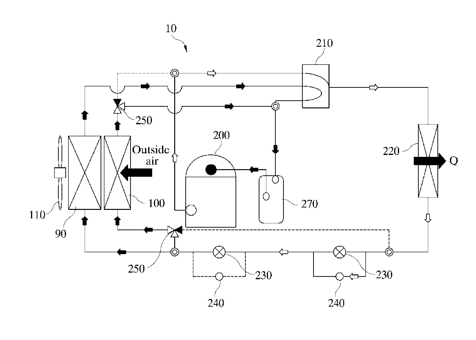
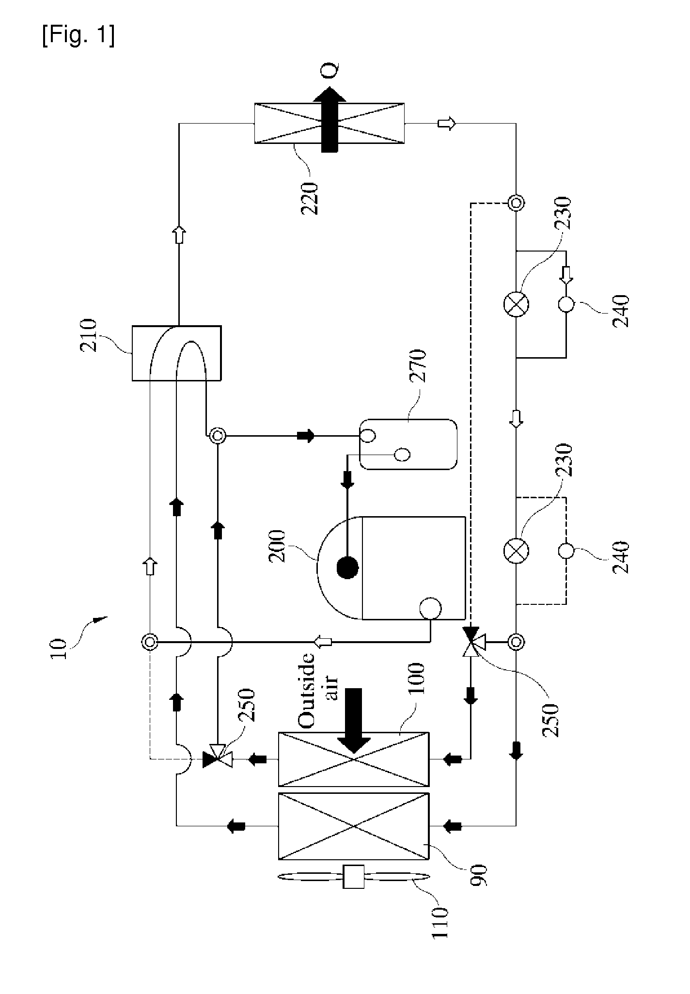
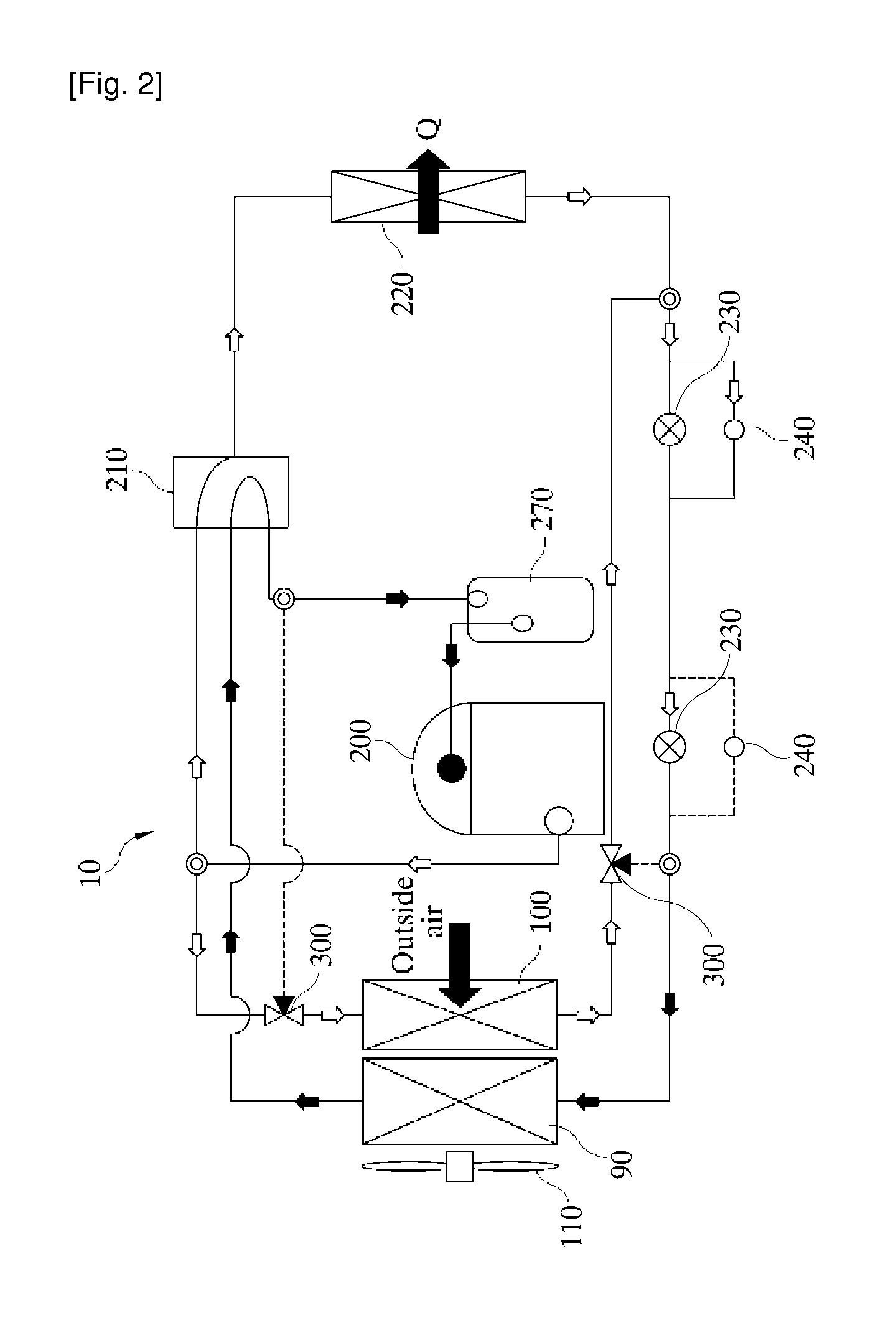
TECHNICAL FIELD[0001]The present invention relates to an alternating type heat pump that has first to third rows of outdoor unit coils adapted to selectively perform the functions of an evaporator and a condenser in accordance with the outdoor conditions and the load variations, thereby improving the performance of the heat pump, and that is capable of allowing the first to third rows of outdoor unit coils to be operated as a condenser in an alternating manner under the conditions where frost on the outdoor unit coils may be formed especially in winter seasons, thereby basically preventing the conditions on which the frost is formed.BACKGROUND ART[0002]FIG.1 shows a schematic circuit diagram showing a standard heating operation of a heat pump according to a conventional practice (which is disclosed in Korean Patent Registration No. 10-0965057 entitled ‘heat pump’ as filed by the same applicant as this invention, wherein the heat pump 10 includes a compressor 200, a four-way valve 21...

Claims


Application Information

Patent Timeline
IPC IPC(8): F25B30/02
CPCF25B30/02F25B49/02F25B47/02F25B13/00F25B2313/0251F25B2313/02533F25B2313/02741
Inventor JEON, CHANG DUK
Owner JEON CHANG DUK
Why Eureka
Eureka Blog
Learn More