Eureka AIR delivers breakthrough ideas for toughest innovation challenges, trusted by R&D personnel around the world.

Cooling system for engine room

Active Publication Date: 2015-11-19
HYUNDAI MOTOR CO LTD
View PDF4 Cites 1 Cited by
  • Summary
  • Abstract
  • Description
  • Claims
  • Application Information

AI Technical Summary

Benefits of technology

The present invention is about a vehicle engine cooling system that increases the cooling performance of a vehicle with a simple structure. The system is designed to enhance the cooling performance of an engine room, making it more efficient. This can be beneficial for vehicles that need to maintain a stable temperature during operation. Overall, the invention improves the performance and efficiency of vehicle engines.

Problems solved by technology

However, simple optimization of heat flow with respect to an engine room layout can improve partial performance such as engine cooling and prevention of heat damage but it cannot obtain a sufficient improvement in terms of an overall engineering performance of an engine room, namely, in a comprehensive aspect such as fuel efficiency, emission, acoustics, aerodynamics, and the like.
Also, the related art obtains desired effects of improving cooling performance and efficiency through optimization of a structure and disposition of a cooling module (tilting of a cooling fan, or the like), application of an active air flap, optimization of a disposition and structure of an air guide, and the like, but improvement effects and range thereof in a comprehensive aspect of an engine room are limited and, actually, there is a limitation in distributing heat flow to the right position due to complicated engine room flow characteristics.

Method used


Image

  • Cooling system for engine room
  • Cooling system for engine room
  • Cooling system for engine room

Examples


Embodiment Construction

[0031]Reference will now be made in detail to various embodiments of the present invention(s), examples of which are illustrated in the accompanying drawings and described below. While the invention(s) will be described in conjunction with exemplary embodiments, it will be understood that the present description is not intended to limit the invention(s) to those exemplary embodiments. On the contrary, the invention(s) is / are intended to cover not only the exemplary embodiments, but also various alternatives, modifications, equivalents and other embodiments, which may be included within the spirit and scope of the invention as defined by the appended claims.

[0032]In the following detailed description, only certain exemplary embodiments of the present invention have been shown and described, simply by way of illustration.

[0033]As those skilled in the art would realize, the described embodiments may be modified in various different ways, all without departing from the spirit or scope o...


PUM


Abstract

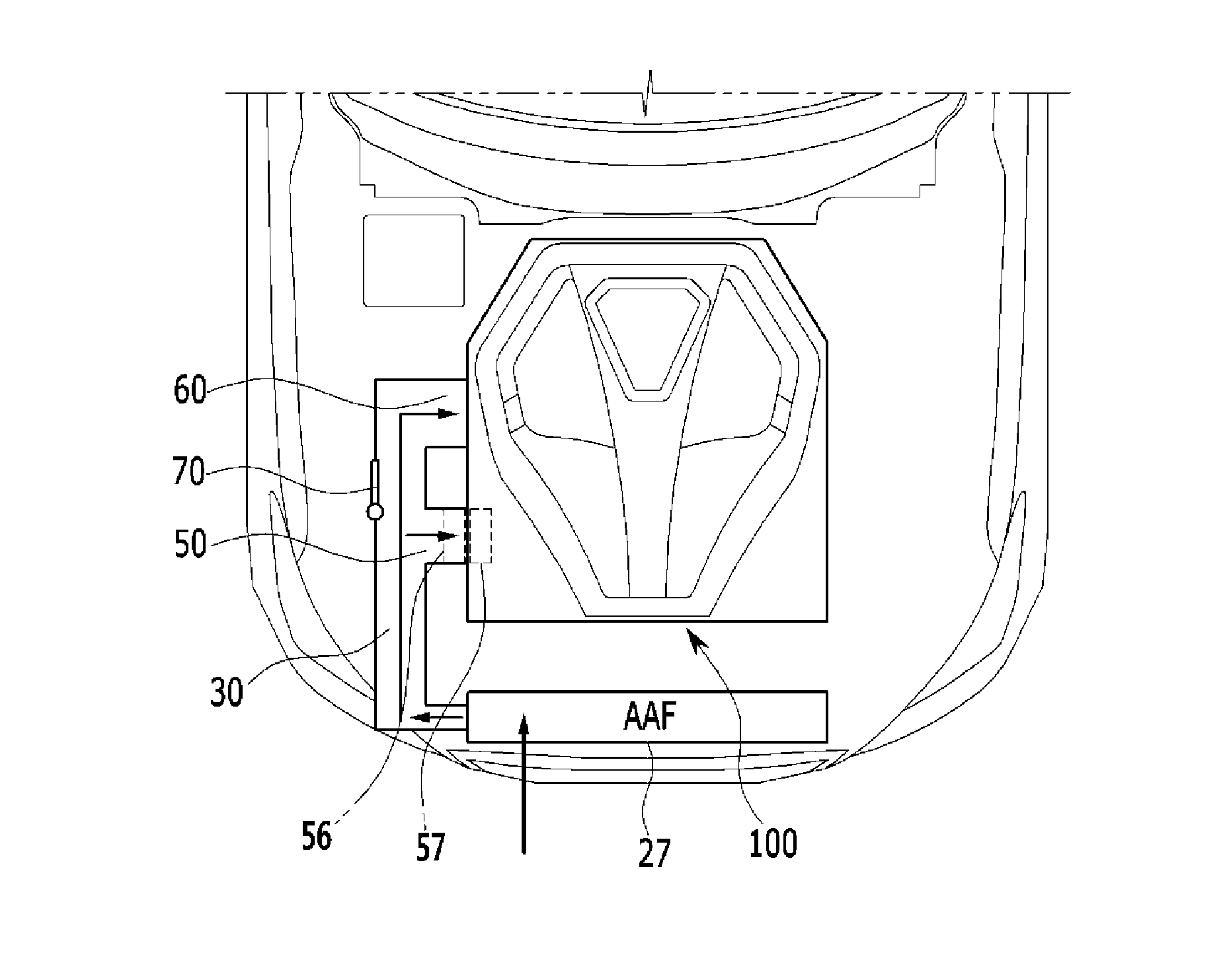
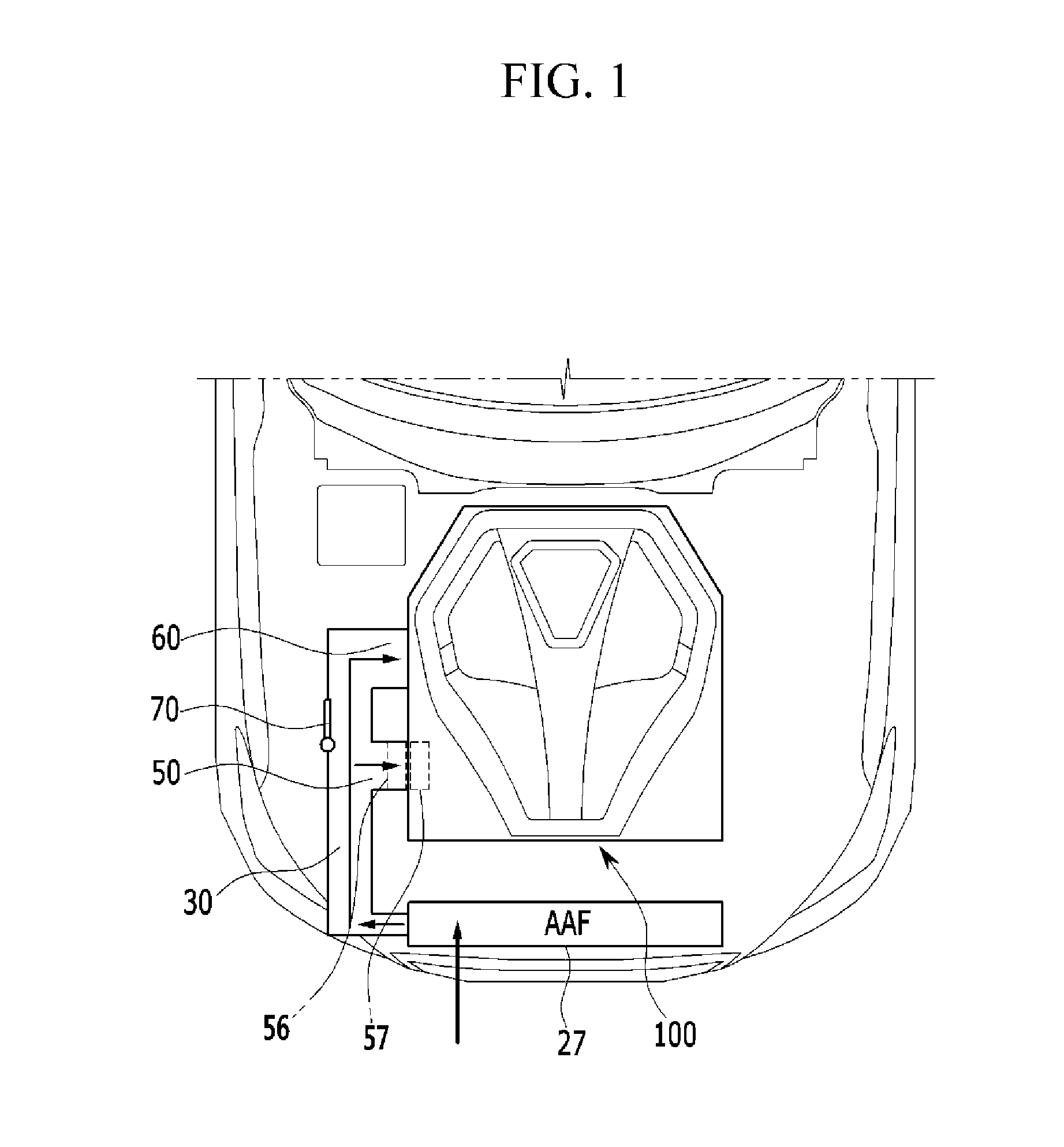
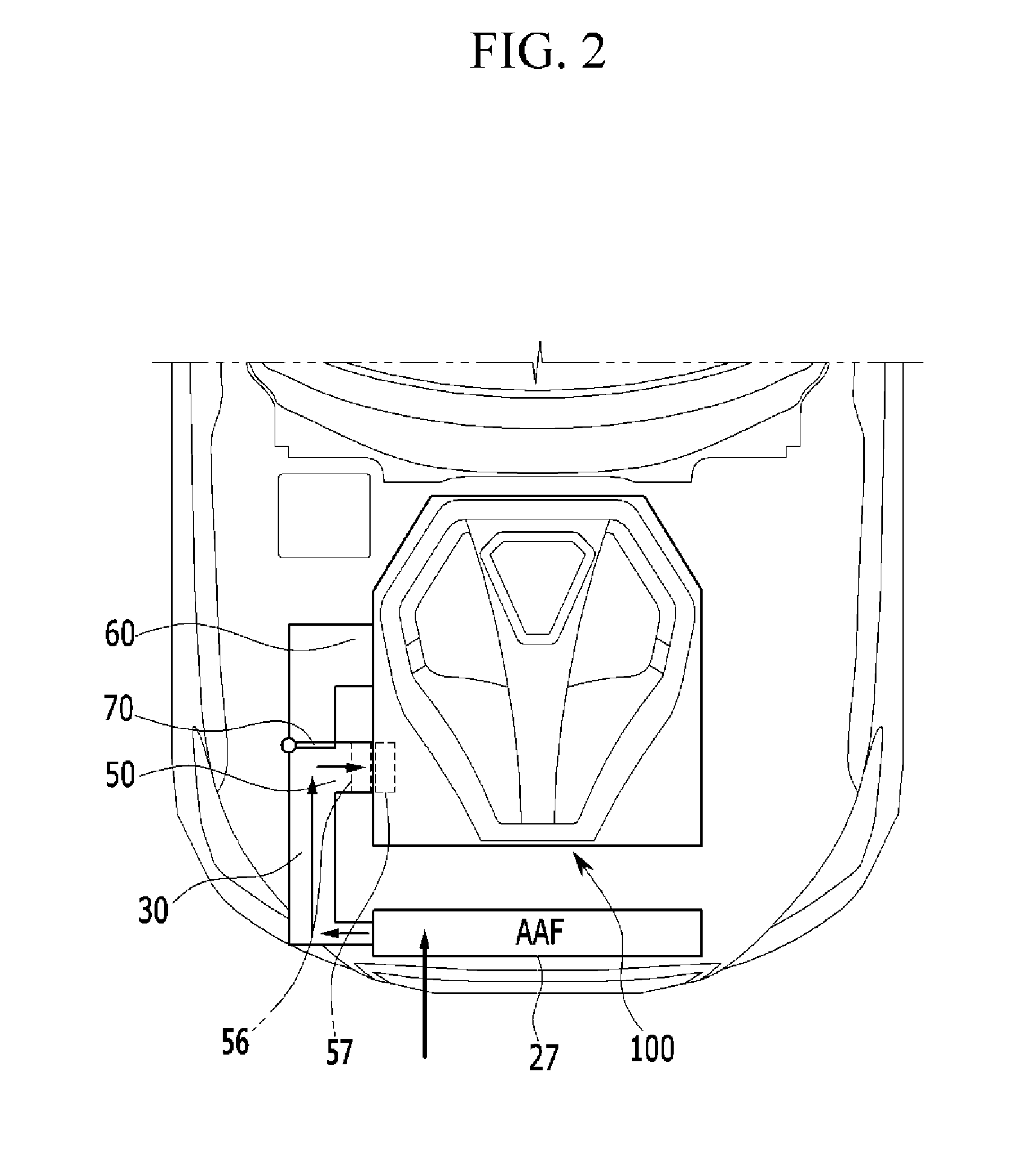
An engine room cooling system may include an encapsulation covering an intake manifold and an exhaust manifold of an engine of a vehicle, a main duct guiding traveling wind flowing into the vehicle to a side of the encapsulation, an encapsulation intake duct branched from the main duct and formed toward the intake manifold within the encapsulation, an encapsulation exhaust duct branched from the main duct and formed toward the exhaust manifold within the encapsulation, and an intake duct valve disposed adjacent to the encapsulation intake duct and controlling air flow from the main duct to the encapsulation intake duct or to the encapsulation exhaust duct.

Description

CROSS-REFERENCE TO RELATED APPLICATION[0001]The present application claims priority to and the benefit of Korean Patent Application No. 10-2014-0057017 filed on May 13, 2014, the entire contents of which is incorporated herein for all purposes by this reference.BACKGROUND OF THE INVENTION[0002]1. Field of the Invention[0003]The present invention relates to a vehicle engine cooling system and, more particularly, to a vehicle engine cooling system capable of enhancing cooling performance of a vehicle with simple structure.[0004]2. Description of Related Art[0005]A vehicle is structurally divided into a vehicle body and a chassis.[0006]Among them, the vehicle body is a part including an engine room and forming an appearance of a vehicle, and, in general, an engine, a transmission, a cooling device, various accessory elements, and the like, are installed in the engine room.[0007]The engine room is a space in which an engine heated to have a high temperature during running is installed, ...

Claims


Application Information

Patent Timeline
IPC IPC(8): F01P1/00
CPCF01P2001/005F01P1/00F02M35/161
Inventor NAM, JONGWOOCHUNG, HANSHINLEE, JOONHOCHO, HYUN
Owner HYUNDAI MOTOR CO LTD
Why Eureka
Eureka Blog
Learn More