Eureka AIR delivers breakthrough ideas for toughest innovation challenges, trusted by R&D personnel around the world.

Air-conditioner system for vehicle and method for controlling same

Active Publication Date: 2016-07-07
HANON SYST
View PDF4 Cites 3 Cited by
  • Summary
  • Abstract
  • Description
  • Claims
  • Application Information

AI Technical Summary

Benefits of technology

The present invention solves the problem of sudden changes in refrigerant flow rate and hunting in an air-conditioner system for vehicles. The invention controls the target superheat degree of the system based on the amount of refrigerant discharged from the compressor, and restricts changes in the refrigerant flow rate at the electronic expansion valve. This prevents performance deterioration of the system and stabilizes it by restraining changes in superheat degree in areas where the amount of refrigerant discharged from the compressor varies. This results in improved cooling performance inside the vehicle and reduces hunting.

Problems solved by technology

Under such a condition, if the degree of opening of the electronic expansion valve 3 is also changed, it is difficult to control the flow rate of the refrigerant and it increases change in the flow rate of the refrigerant.
Because of such problems, hunting that the refrigerant beats and generates pulsation occurs, and it causes instability of the system.
When the compressor 1 is turned off, the temperature of the air discharged to the inside of the vehicle increases while the temperature of the air discharged from the evaporator 4 increases, hence cooling performance is deteriorated.
This is why the system becomes unstable.
In such an air-conditioner system, cooling performance is deteriorated in a superheat degree over-increase section where the superheat degree increases above the optimum superheat degree (optimum refrigerant flow rate).
Therefore, a control range of the optimum superheat degree area becomes narrow, hence instability possibility of the system increases when a common target superheat degree is controlled.
In other words, the conventional air-conditioner system has a disadvantage in that the system becomes unstable when the target superheat degree is controlled through the electronic expansion valve 3 in the same way as the high load condition, namely at the time of the maximum discharge of the compressor, even though the refrigerant discharge amount is small in the low load condition of the air-conditioner system, namely in the variable area of the compressor 1 where the ECV duty lowers.

Method used


Image

  • Air-conditioner system for vehicle and method for controlling same
  • Air-conditioner system for vehicle and method for controlling same
  • Air-conditioner system for vehicle and method for controlling same

Examples


Embodiment Construction

[0033]Reference will be now made in detail to the preferred embodiment of the present invention with reference to the attached drawings.

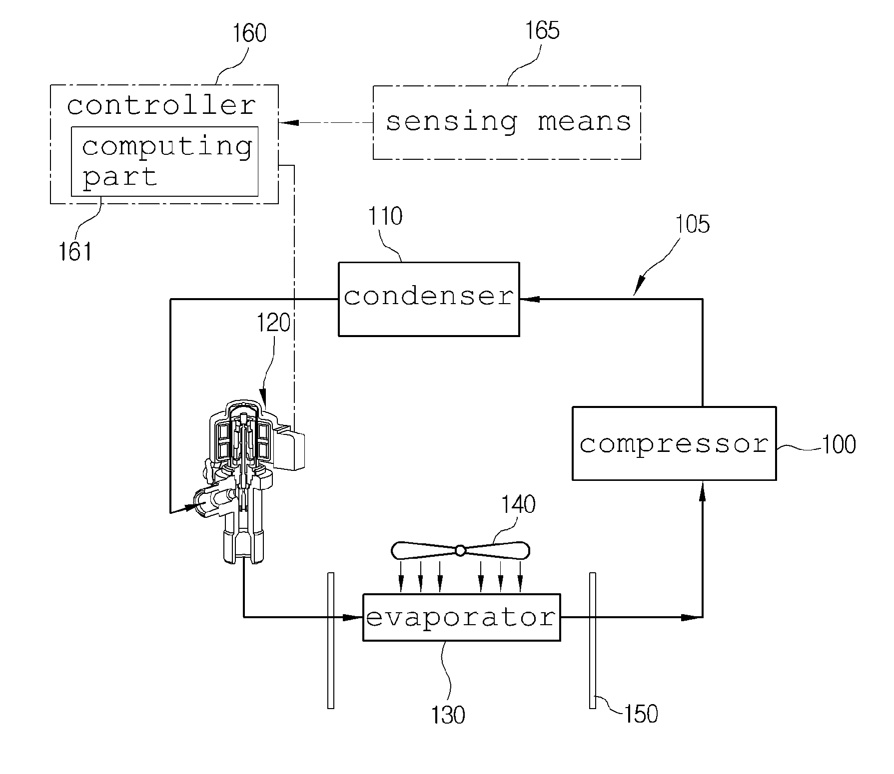
[0034]First, an air-conditioner system for a vehicle according to a first preferred embodiment of the present invention is configured of a compressor 100, a condenser 110, an electronic expansion valve 120 and an evaporator 130 which are connected to a refrigerant pipe 105 in order, and includes a controller 160 for controlling the electronic expansion valve 120.

[0035]The compressor 100 inhales and compresses gas-phase refrigerant discharged from the evaporator 130 and discharges the gas-phase refrigerant in a high-temperature and high-pressure state to the condenser 110 while receiving a driving power from a driving power supply source, such as an engine or a motor to operate.

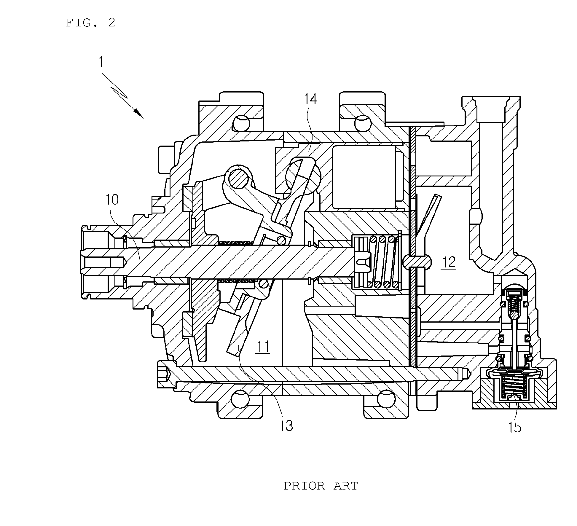
[0036]The compressor 100 is a variable capacity compressor 100. Referring to FIG. 2, the compressor 100 will be described in brief. The compressor 100 includes: a rotary shaft...


PUM


Abstract

The present invention relates to an air-conditioner system for a vehicle and a method for controlling the same, and more particularly, to an air-conditioner system for a vehicle and a method for controlling the same which can change a target superheat degree depending on variation in an amount of refrigerant discharged from a compressor, namely, gradually decrease the target superheat degree by stages as the amount of refrigerant discharged from the compressor decreases, and control an electronic expansion valve based on the target superheat degree dropping by stages, thereby preventing performance degradation of an air conditioner and stabilizing the system by restraining a change in the superheat degree in an area where an amount of refrigerant discharged from a compressor varies.

Description

TECHNICAL FIELD[0001]The present invention relates to an air-conditioner system for a vehicle and a method for controlling the same, and more particularly, to an air-conditioner system for a vehicle and a method for controlling the same which can change a target superheat degree depending on variation in an amount of refrigerant discharged from a compressor, namely, gradually decrease the target superheat degree by stages as the amount of refrigerant discharged from the compressor decreases, and control an electronic expansion valve based on the target superheat degree dropping by stages.BACKGROUND ART[0002]In general, as shown in FIG. 1, an air-conditioner system for a vehicle includes: a compressor 1 for compressing and discharging refrigerant; a condenser 2 for condensing the refrigerant of high pressure discharged from the compressor 1; an expansion valve 3 for throttling the refrigerant condensed and liquefied in the condenser 2; an evaporator 4 for exchanging heat between the ...

Claims


Application Information

Patent Timeline
IPC IPC(8): F25B49/02B60H1/32F25B41/06
CPCF25B49/022F25B41/062B60H1/3205B60H2001/3279F25B2700/13F25B2600/2513F25B2341/0653F25B2600/023B60H1/3216B60H2001/3242B60H2001/3285Y02B30/70F25B41/34F25B2600/21F25B41/35
Inventor KO, JAEWOOHAN, GYUIKEOM, SAEDONGYOON, KILSANGKANG, INKEUN
Owner HANON SYST
Why Eureka
Eureka Blog
Learn More